According to CEO Tony Bates, Skype has topped 250 million monthly users worldwide, becoming the global standard for video web conferencing. The possibilities for businesses are obvious and expansive - but how to keep all those minds and divergent thinking styles on the same page? CS Odessa is rising to that challenge with their new Remote Presentation for Skype solution for ConceptDraw MINDMAP ®.
Presentations are an established way of sharing ideas across a workforce, there′s no better software to create them than ConceptDraw MINDMAP Using the Remote Presentation for Skype solution, you can include a workforce that is spread across the globe. What′s more, MINDMAP′s ability to present an array of document types means you can work with Microsoft® Word®, Microsoft PowerPoint®, and Microsoft Project® files, or any number of mind map formats. The possibilities are limited only by the user′s imagination.
Thanks to the Remote Presentation for Skype solution, ConceptDraw MINDMAP users can present their documents live via Skype, allowing coworkers in other cities, countries, even continents to view their briefing while hearing their voice.
This brief tutorial video will take you through all the steps you need to start viewing your colleagues MINDMAP presentations through Skype.
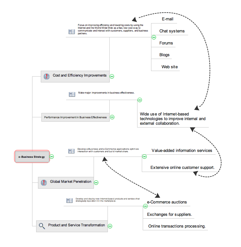
Sample 1. Remote Presentation for Skype - E-business Strategy
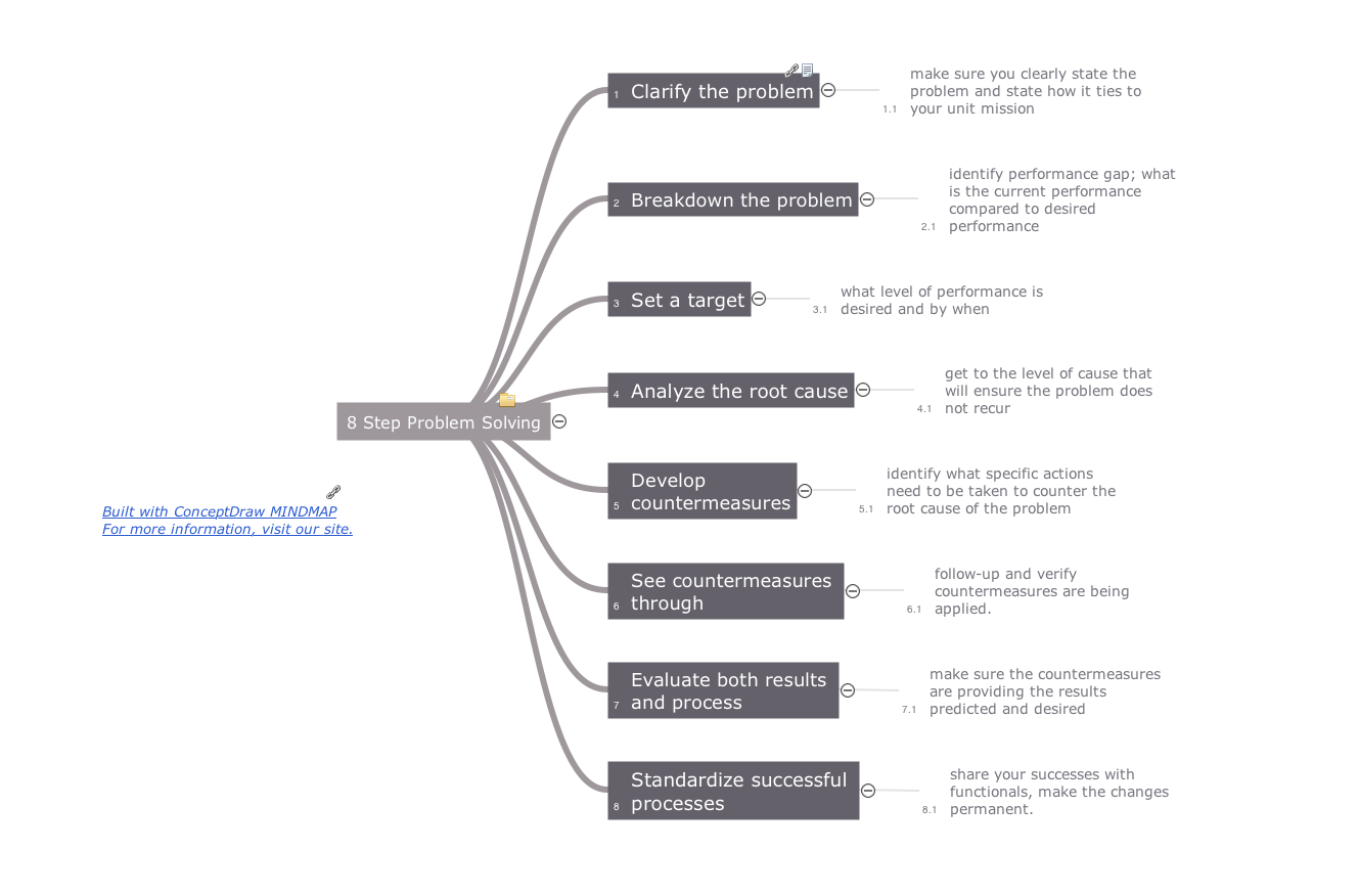
ConceptDraw MINDMAP with Quality mindmaps solution as a demonstration of the creative approach to quality management in daily work of quality management team.
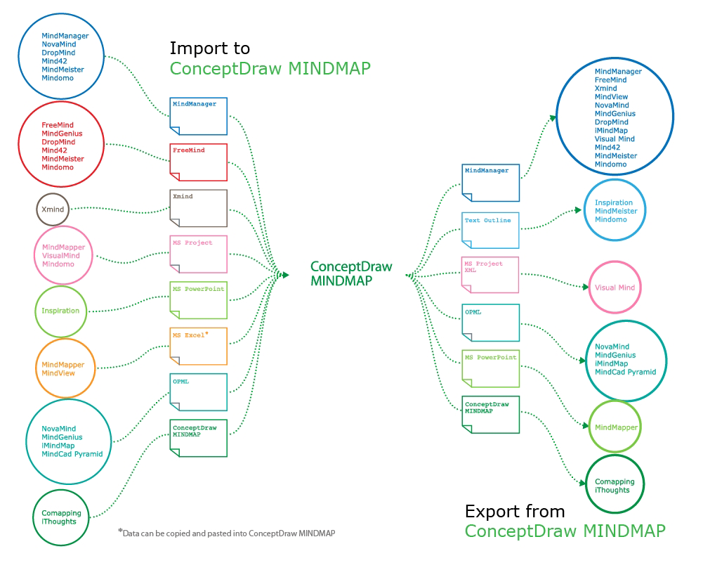
Data Exchange - Tools to exchnage data files of major mindmapping software for team collaboration.
The Mind Map Exchange solution allows you to share mind maps with others who have 3rd party mind map applications.
Picture: How to exchange data files of major mind mapping software?
The Quality Mind Map Solution extends ConceptDraw MINDMAP with the addition of a number of Quality Management Mind Maps (Presentations, Meeting Agendas, and problem-solving techniques).
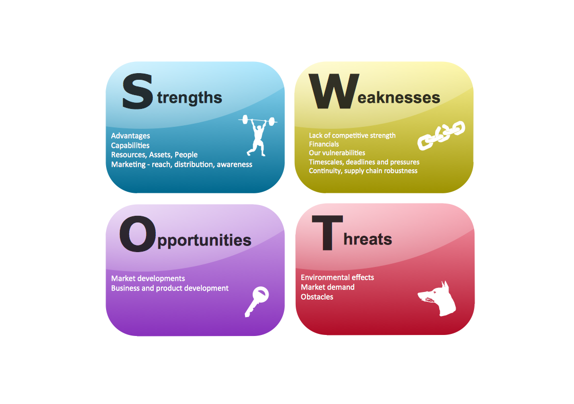
A lot of business process techniques are able to be applied in regular life. Although this tool is considered to be used for business purposes, you can make a SWOT template for yourself. In fact, any obstacle might become a subject for SWOT analysis.
ConceptDraw solution for SWOT analysis solution provides a power visual maintenance of a SWOT analysis. It is a procedure of strategic planning made to discover the Strengths, Weaknesses, Opportunities, and Threats business meet. This mind map template for ConceptDraw MINDMAP isually maintains investigation of good and bad factors. For example, factors that provides an advantage over others are strength; factors that brings a disadvantage are factors of weakness. After the analysis is finished, transfer your data to create a SWOT matrix in ConceptDraw DIAGRAM.
A competent delegation of responsibilities between workers guarantees business success in most cases. At first sight, it might seem that workflow diagram symbols are quite similar to a regular flowchart. But workflow diagram is a more accurate way to present working processes.
Workflow diagrams are helpful for a working process analyzation, to depict a pathway of process issues, personalize responsibilities and identify resources that will help to optimize a workflow. Generally, Workflow diagram deploys flowchart symbols for displaying work process steps and relationships. But, often it require some additions and improvements to become more professional and illustrative. The Workflow solution for ConceptDraw DIAGRAM provides the user with a big library of symbols that are designed especially for workflow diagrams.
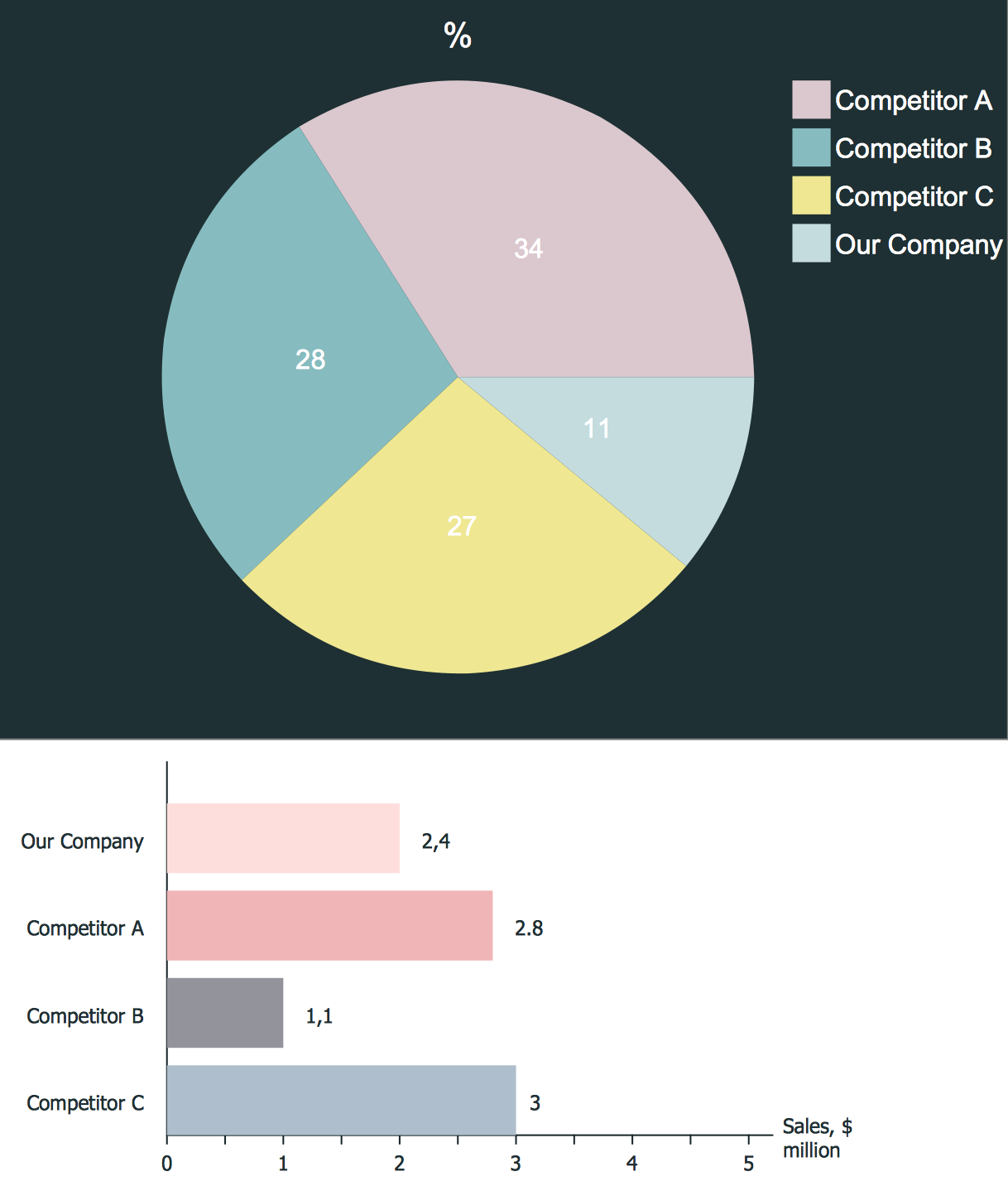
Competitor analysis is a first and obligatory step in elaboration the proper corporate marketing strategy and creating sustainable competitive advantage. Use powerful opportunities of numerous solutions from ConceptDraw Solution Park for designing illustrative diagrams, charts, matrices which are necessary for effective competitor analysis.
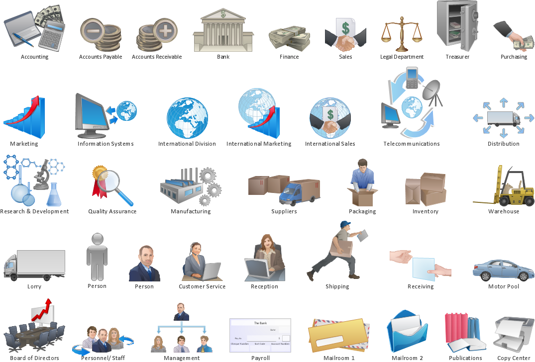
Choose the business illustration design you love best, and sign our design your own style with Business and Finance Illustrations library from ConceptDraw DIAGRAM.
The Business and Finance solution contains 12 vector clipart libraries: Advertising, Business, Business people clipart, Business people figures, Currency, Mail and post, Management, Marketing, Money, Office, Project management, Time
Stakeholders are the groups of people or organizations whose contribution matters to the organization's success, this can be labour participation, financial participation, dissemination of information about organization, etc. So, the employees of the company, its suppliers, customers, media, public organizations, state authorities, all they are stakeholders of the company.
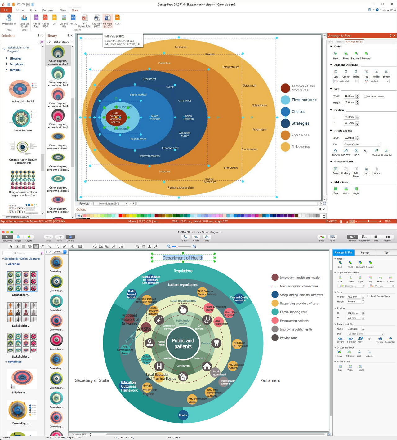
ConceptDraw DIAGRAM diagramming and vector drawing software extended with Stakeholder Onion Diagrams Solution from the Management Area of ConceptDraw Solution Park is a powerful stakeholder mapping tool which allows easy create Stakeholder Onion diagrams and maps depicting the layers of a project, relationships of stakeholders to a project goal, and relationships between stakeholders.
Picture: Onion Diagram as Stakeholder Mapping Tool
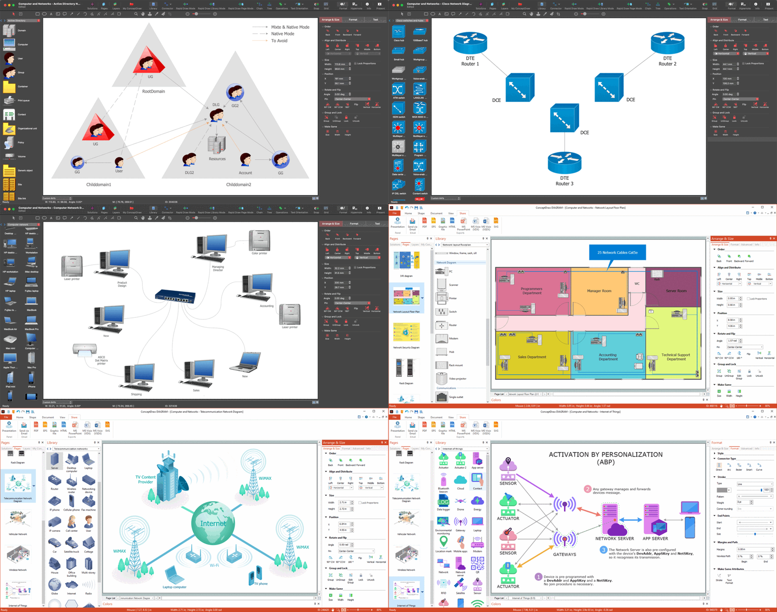
Why do you need network visualizations? 🔸 Unlock the full potential of network visualization with our in-depth guide on using the ConceptDraw Network Visualization Tool. ✔️ Explore features, tips, and best practices to create stunning visual representations of your network architecture
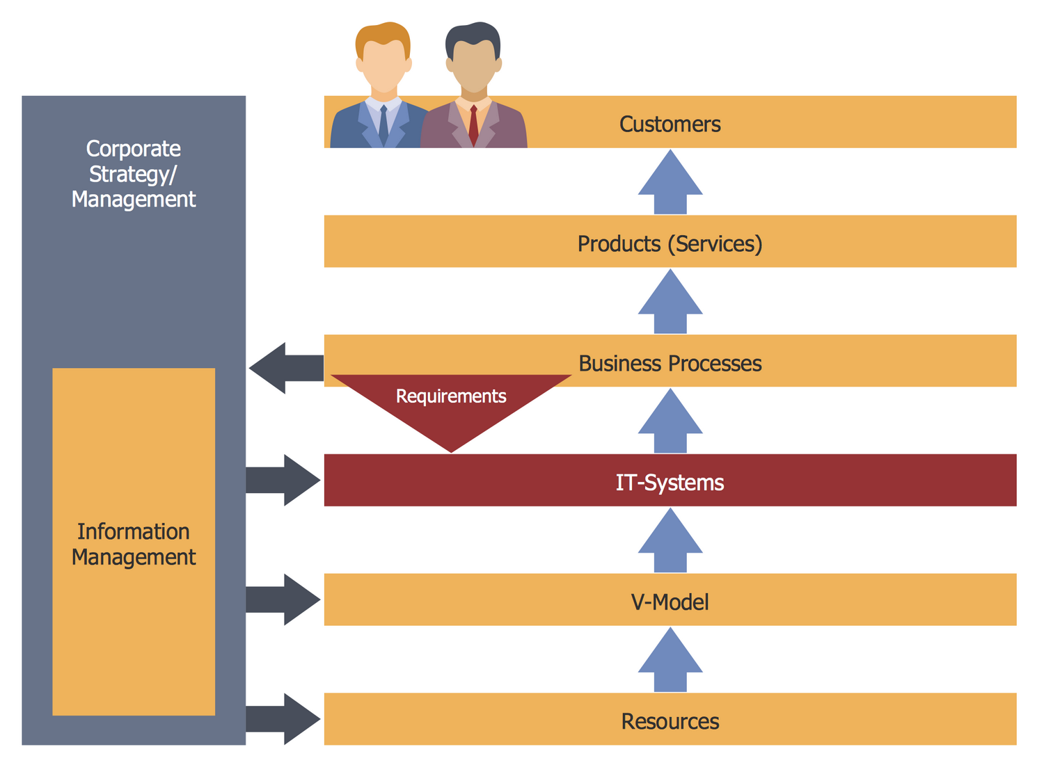
ConceptDraw DIAGRAM software extended with Workflow Diagrams solution ideally suits for effective business process optimization, for determination the opportunities for improvements and enhancements the processes, cost reduction and cost savings.