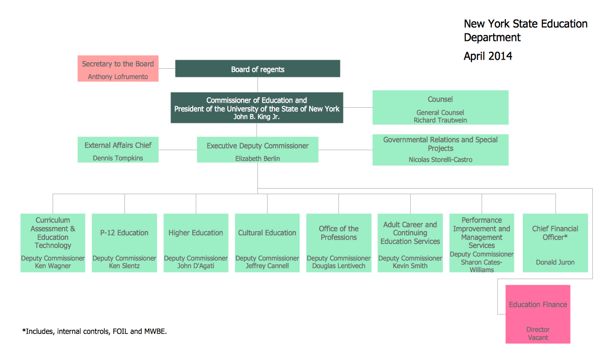
Example 1. Organizational Chart - New York State Education Department
An organizational chart of any complexity can be easily drawn in ConceptDraw DIAGRAM thanks to the extensive drawing tools of Organizational Charts Solution. It's enough to just look at the Organizational Chart library of predesigned objects to understand what it contains all necessary objects for quick Organizational Chart drawing.
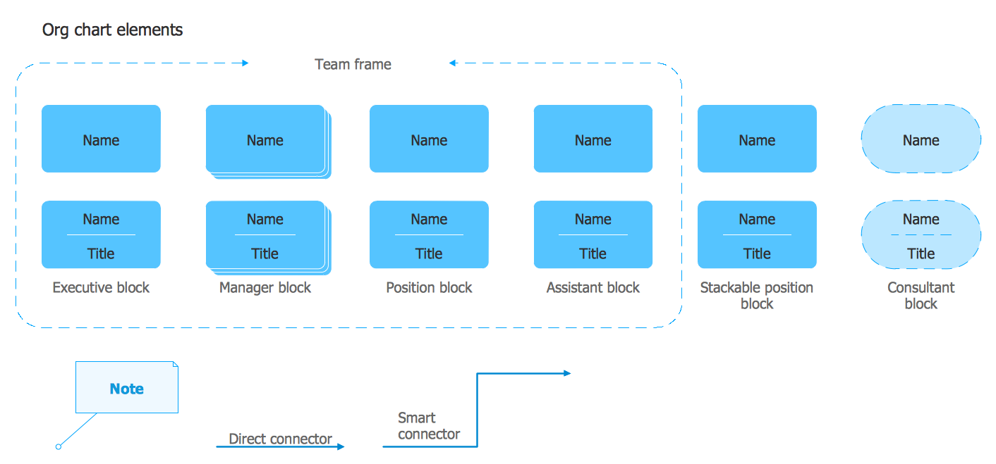
Example 2. Organizational Chart Library Design Elements
Organizational Charts solution provides also a set of predesigned templates and samples which are available for viewing and editing from ConceptDraw STORE. All you have to do is open a suitable template and fill it out according to your organization's structure.
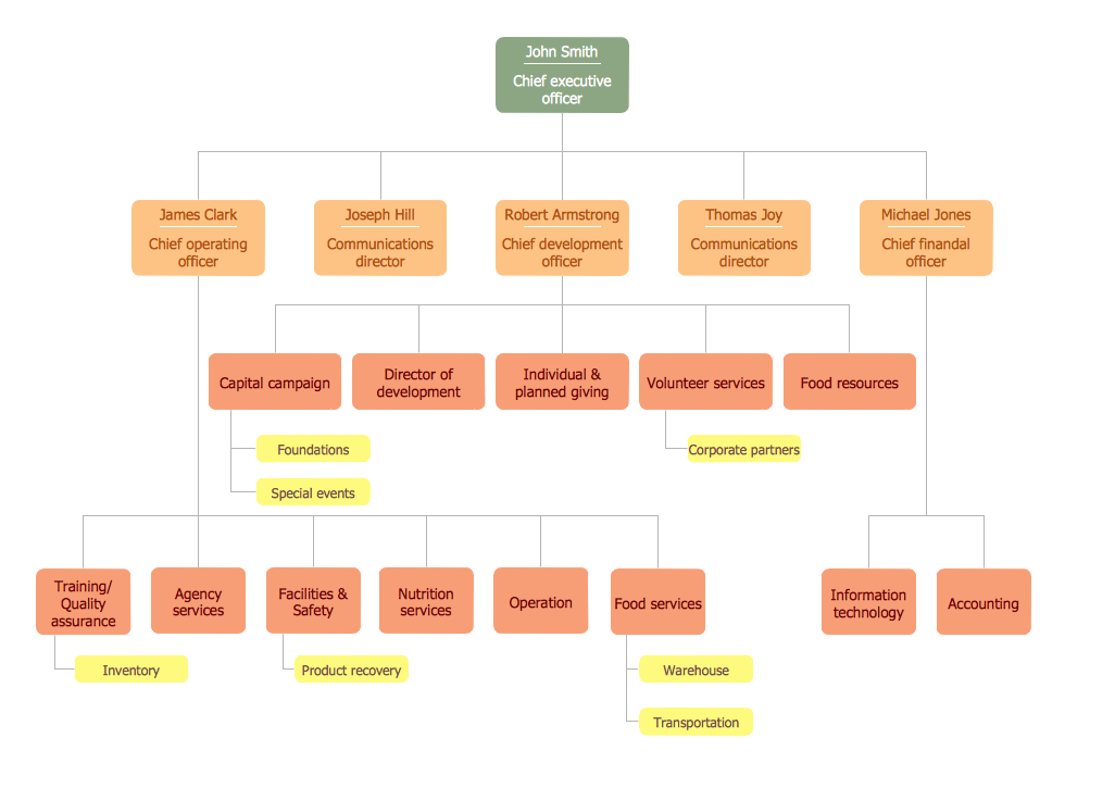
Example 3. Organizational Chart - Foodbank
The following features make ConceptDraw DIAGRAM the best Organizational Chart software:
- You don't need to be an artist to draw professional looking charts in a few minutes.
- Large quantity of ready-to-use vector objects makes your drawing Organizational Charts quick and easy.
- Great number of predesigned templates and samples give you the good start for your own charts.
- ConceptDraw DIAGRAM provides you the possibility to use the grid, rules and guides. You can easily rotate, group, align, arrange the objects, use different fonts and colors to design your organizational chart exceptionally looking.
- All ConceptDraw DIAGRAM documents are vector graphic files and are available for reviewing, modifying, and converting to a variety of formats: image, HTML, PDF file, MS PowerPoint Presentation, Adobe Flash, MS Visio.
- Using ConceptDraw STORE you can navigate through ConceptDraw Solution Park, managing downloads and updates. You can access libraries, templates and samples directly from the ConceptDraw STORE.
- If you have any questions, our free of charge support is always ready to come to your aid.
How to Create an Organizational Chart in ConceptDraw DIAGRAM
ConceptDraw DIAGRAM simplifies organizational chart creation with a set of pre-designed templates. All you need to do is open a suitable template and fill it out according to the structure of your organization. Below are the few basic steps when drawing an organizational chart with ConceptDraw DIAGRAM.
- We recommend you to start with the basic Org Chart template provided in the Organizational Chart solution.
- Arrange the chart elements within a workspace using a mouse.
- Add extra elements to the chart by dragging them from the library and connecting them using the Smart Connectors tool.
- Select any element and type to add a text.
- Once the organizational chart is completed you can export it into Excel®, Word®, or PowerPoint® in a few simple clicks.
Create an Organizational Chart Using MS Office®
The simplest way to depict an organizational structure is to keep it
in a data file that lists all of the employees and who they obey.
Commonly Excell® or Word® software is used to manage HR data.
Alternatively, you can use ConceptDraw MINDMAP for keeping data on organization structure and then ConceptDraw DIAGRAM for presenting the results as a business graphic document. You may store all your employee information structured in a radial mind map form. ConceptDraw OFFICE makes it easy to take a mind map file and turn it into a professional-looking organizational chart automatically. Moreover, you can rearrange, add, or move departments, positions, as well as set new interrelations - just with simple drag-and-dropping.
TEN RELATED HOW TO's:
ConceptDraw Pyramid Diagram software allows drawing column charts using predesigned objects or drawing tools.
Picture: Pyramid Diagram
Related Solutions:
ConceptDraw DIAGRAM is the world’s premier cross-platform business-diagramming tool. Many, who are looking for an alternative to Visio, are pleasantly surprised with how well they can integrate ConceptDraw DIAGRAM into their existing processes. With tens of thousands of template objects, and an easy method for importing vital custom objects from existing Visio documents, ConceptDraw DIAGRAM is a powerful tool for making extremely detailed diagrams, quickly and easily.
Picture: ConceptDraw DIAGRAM : Able to Leap Tall Buildings in a Single Bound
Related Solution:
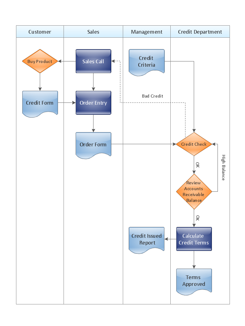
Definition, examples, layout options, best practices, and common mistakes for cross functional flowcharts (swimlane diagrams).
Picture: Cross Functional Flowchart (Swimlane Diagram): Definition, Structure, Examples, and How to Create
Related Solution:
Create bar charts for event management problem solving and visual data comparison using the ConceptDraw DIAGRAM diagramming and vector drawing software extended with the Bar Graphs Solution from the Graphs and Charts area of ConceptDraw Solition Park.
Picture: Bar Diagrams for Problem Solving.Create event management bar charts with Bar Graphs Solution
Related Solution:
Working with personnel might be difficult if you are not prepared enough. To explain your workers all the details of communication with customers, you can draw an order process flowchart which will describe every step of the process and answer all the questions that might appear. You can view a lot of business process mapping diagram examples here, in ConceptDraw Solution Park.
This business process flow chart is created to illustrate the sample work order process. Before an organization can make some work for a person, the customer work order request must be completed. It is needed for tracking and accountability objectives. We used this business process flowchart to show a certain tasks and actions assumed by an organization. This flowchart depicts the outside inputs that are needed to launch a process, and ways the organization delivers its outputs. This business process flowchart was created with a help of ConceptDraw Business Process Mapping solution.
Picture: Work Order Process Flowchart. Business Process Mapping Examples
Related Solution:
This mind map demonstrates how the well-known Total Quality Management (TQM) methodology can be presented in a mind map. Using mind mapping for quality management is a creative approach that allows one to structure all key quality points on the one page.
Picture: Total Quality Management
Related Solution:
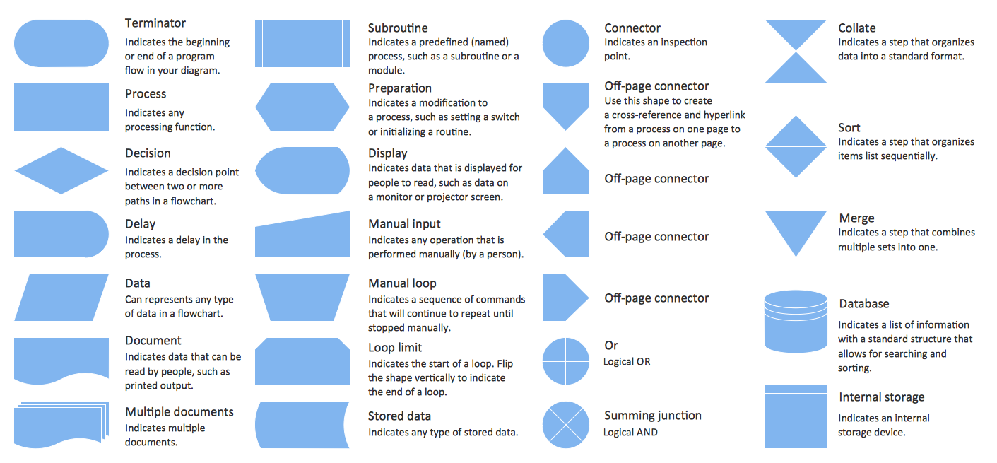
While creating flowcharts and process flow diagrams, you should use special objects to define different statements, so anyone aware of flowcharts can get your scheme right. There is a short and an extended list of basic flowchart symbols and their meaning. Basic flowchart symbols include terminator objects, rectangles for describing steps of a process, diamonds representing appearing conditions and questions and parallelograms to show incoming data.
This diagram gives a general review of the standard symbols that are used when creating flowcharts and process flow diagrams. The practice of using a set of standard flowchart symbols was admitted in order to make flowcharts and other process flow diagrams created by any person properly understandable by other people. The flowchart symbols depict different kinds of actions and phases in a process. The sequence of the actions, and the relationships between them are shown by special lines and arrows. There are a large number of flowchart symbols. Which of them can be used in the particular diagram depends on its type. For instance, some symbols used in data flow diagrams usually are not used in the process flowcharts. Business process system use exactly these flowchart symbols.
Picture: Flowchart Symbols: Meaning and Examples
Related Solution:
Analyze each identified action separately in the tree of all actions and then develop a preventive action in response to potential obstacles or circumstances have been identified as a risk.
The PDPC determines the risks when corrective action is not performed correctly. Also, it helps develop descriptions for preventive actions at the level of execution.
Picture: Risk Diagram (Process Decision Program Chart)
Related Solution:
Nova Scotia is one of Canada's three Maritime provinces and constitutes one of the four Atlantic Canada provinces.
The vector stencils library Nova Scotia contains contours for ConceptDraw DIAGRAM diagramming and vector drawing software. This library is contained in the Continent Maps solution from Maps area of ConceptDraw Solution Park.
Picture: Geo Map - Canada - Nova Scotia
Related Solution:
An abstract representation is usually the first thing you will need while developing a database. To understand the ways that databases are structured, you should look through entity-relationship diagram examples and see the notations features and attributes. With an entity-relationship model you can describe a database of any complexity.
This Entity-relationship diagram is a tool for software developers. It enables every element of database to be managed, communicated and tested before release. This ERD was created using symbols advocated by Chen's notation. Because of a linguistic origin of the Chen’s notation, the boxes representing entities could be interpreted as nouns, and the relationships between them are in verb form, shown on a diagram as a diamond.
Picture: Entity Relationship Diagram Examples
Related Solution: