Made with
ConceptDraw
DIAGRAM 18

Conception d'organigramme
Organigramme des symboles, formes, stencils et icônes

Les présentations et documents graphiques professionnels sont plus compréhensibles et clairs s'ils utilisent des thématiques de couleurs distinctes pour leurs différentes composantes.

La présentation par organigramme rend les démonstrations et les explications de processus opérationnels plus flexibles, et offre un aperçu d'un nouveau genre, se démarquant des organigrammes noir et blanc classiques sur papier.

Les meilleures présentations peuvent être obtenues en utilisant les modèles « Conceptdraw » adéquats comme base de départ.

Choisissez simplement l'un d'eux et entrez le texte souhaité dans chaque forme du diagramme. Appliquez moins de couleurs dans le document afin de ne pas le transformer en arc-en-ciel, trois ou quatre sera suffiront, notez également que la modélisation des processus opérationnels ne doivent pas contenir des nuances trop claires. Il est aussi recommandé d'utiliser une même couleur pour des formes identiques au sein de l'organigramme.

Un organigramme est un type de diagramme qui représente un algorithme, un workflow ou processus, montrant les étapes comme des formes de divers types, et leur ordre en les connectant avec des flèches. Ce diagramme:

  1. Représente un algorithme ou un processus
  2. Illustre une solution à un problème donné
  3. Représente les opérations de traitement
  4. Est utilisé en analyse
  5. Est utilisé dans la conception
  6. Est utilisé pour la documentation
  7. Est utilisées dans la gestion d'un processus
  8. Est utilisé pour les programmes dans divers domaines

Les symboles de l'organigramme permettent de visualiser un processus ou un algorithme de programme comme des blocs de différentes formes représentant des étapes/opérations, et reliés par des traits fléchés indiquant la direction du processus.
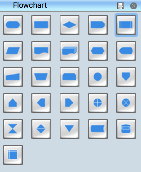
Bibliothèques de symboles d'un organigramme standard

Pic 1. Bibliothèques de symboles d'un organigramme standard

La bibliothèque comprend les 26 symboles standards fournis par l'American National Standard Institute (ANSI) pour la création d'organigrammes.
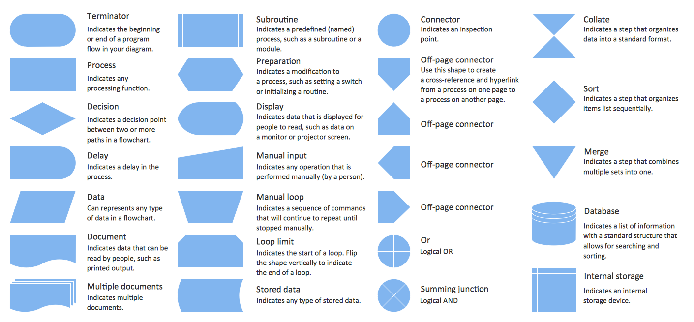
Conception d'organigramme. Organigramme des symboles, formes, stencils et icônes

Pic 2. Eléments pour la conception d'organigrammes. Symboles, formes, stencils et icônes


Comment concevoir des organigrammes à l'aide symboles standards

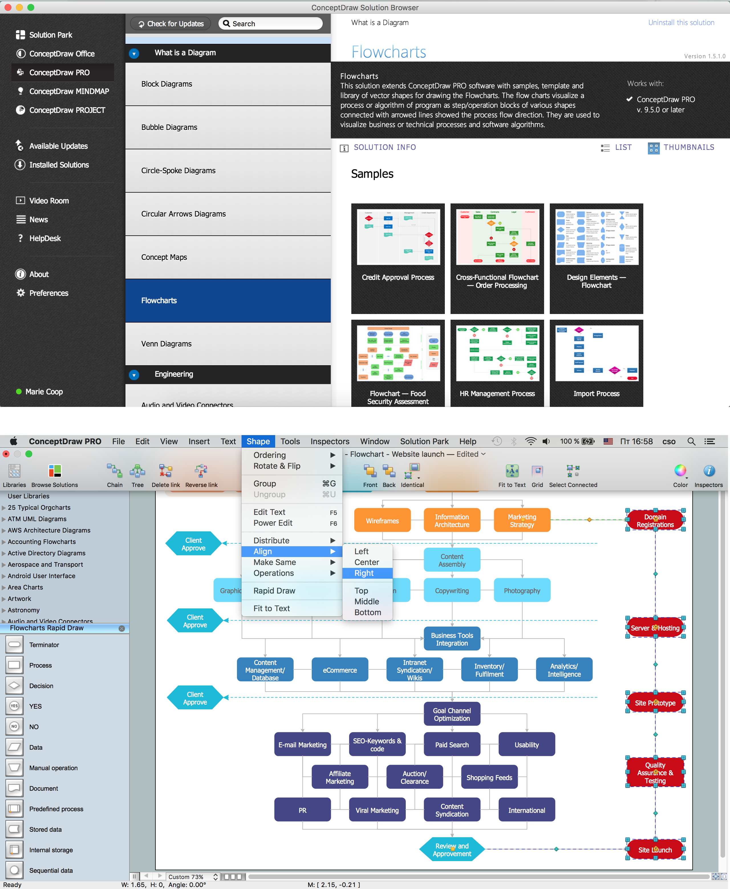
Pour créer un diagramme ConceptDraw, sélectionnez un modèle de diagramme existant dans la partie" Qu'est-ce qu'un schéma ?" . Cette solution contient tous les outils, échantillons et une bibliothèques avec icônes vectoriels permettant de construire un schéma spécifique.

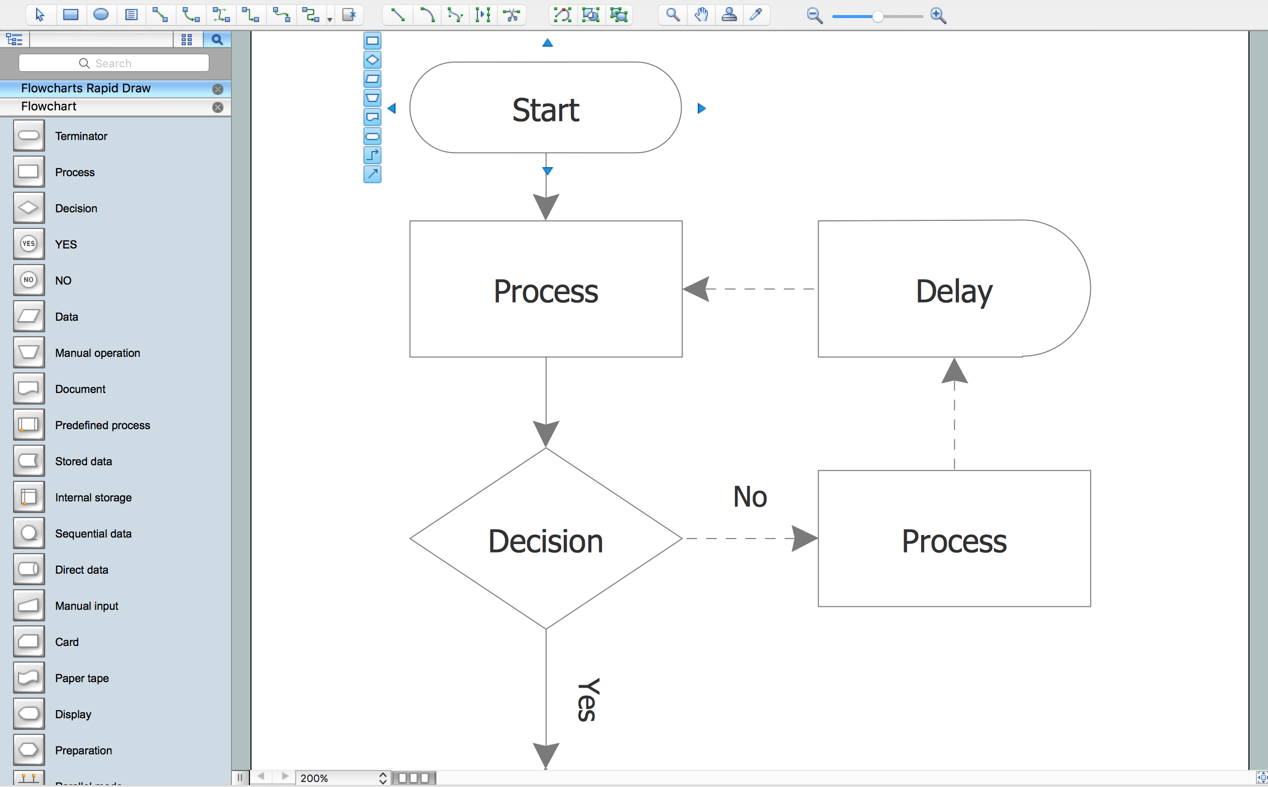
  • L'organigramme devrait être démarré et terminé avec le symbole Correspondant.
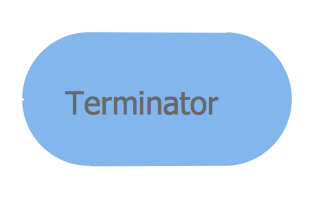
    Organigramme - Correspondant

  • Utilisez le symbole de Décision pour poser une question.

    Organigramme - Décision

  • Le symbole du Processus est utilisé pour les activités ou les étapes de l'action.

    Organigramme - Processus

  • Le symbole de Temporisation est utilisé pour indiquer un retard dans le processus.

    Organigramme - Temporisation

  • Un symbole de référence off-page signifie une référence croisée à partir d'un processus sur la même page, ou, si contenant une lettre ou un numéro, signifiant que ce schémase connecte à ungraphique sur une page différente.

    Organigramme

  • Utilisez les boutons de « Dessin Rapide » pour ajouter automatiquement les symboles du schéma fonctionnel standard.
    Organigramme

  • Les symboles du schéma fonctionnel ajouté avec le « Tracé Rapide de Flêches » sont connectés automatiquement.
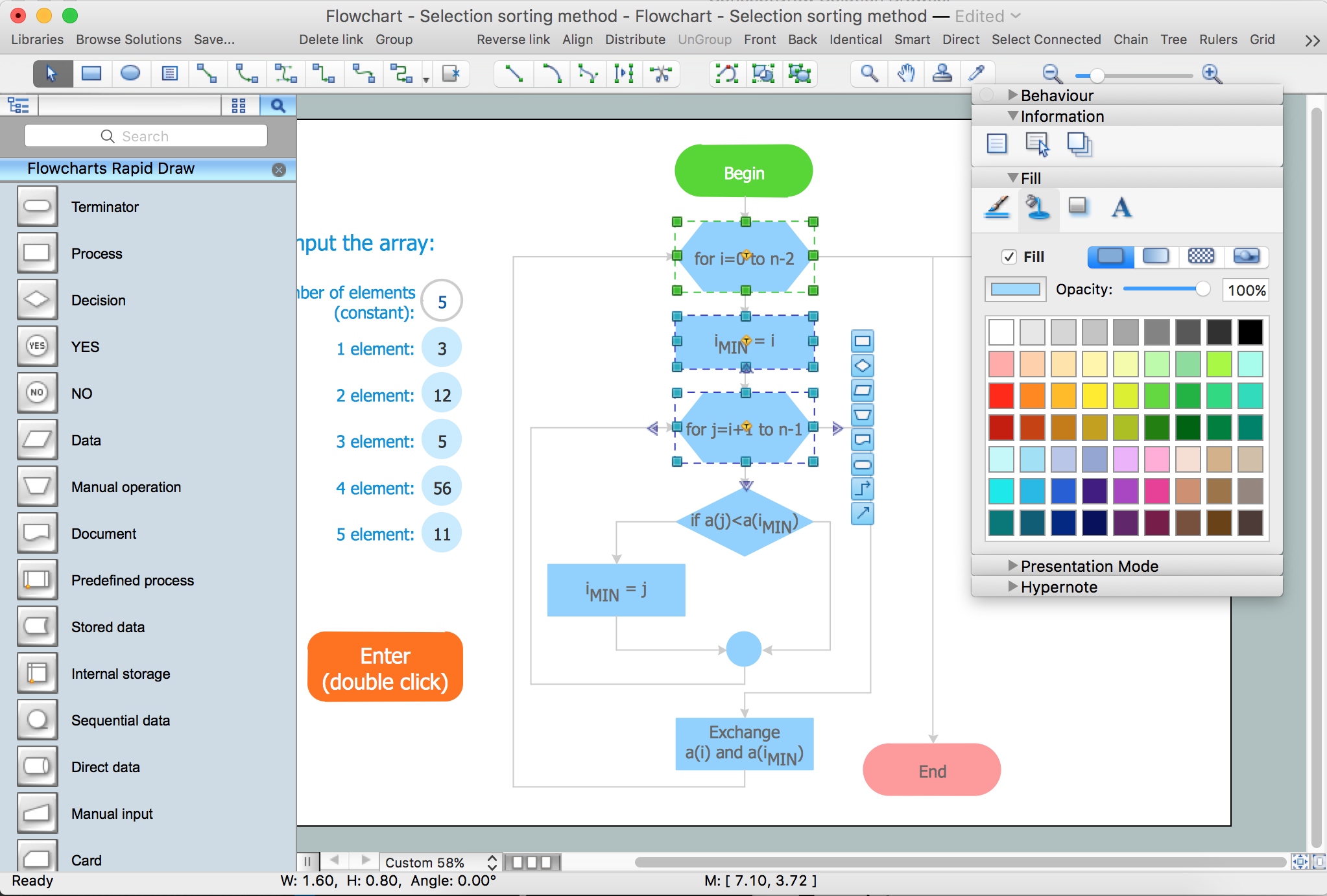
  • Changing the style of your Flowchart in just one click.
    Design flowchart

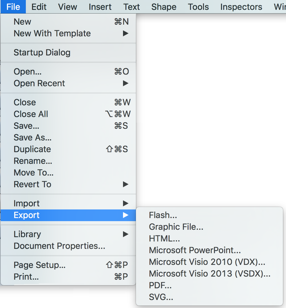
  • Changer le style de votre diagramme en un seul clic. Vous pouvez maintenant partager votre organigramme Complété avec d'autres. Vous pouvez exporter (HTML, PowerPoint MS Visio 2010, 2013) votre résultat visuel en un seul clic.

    Organigramme

Organigramme Exemple

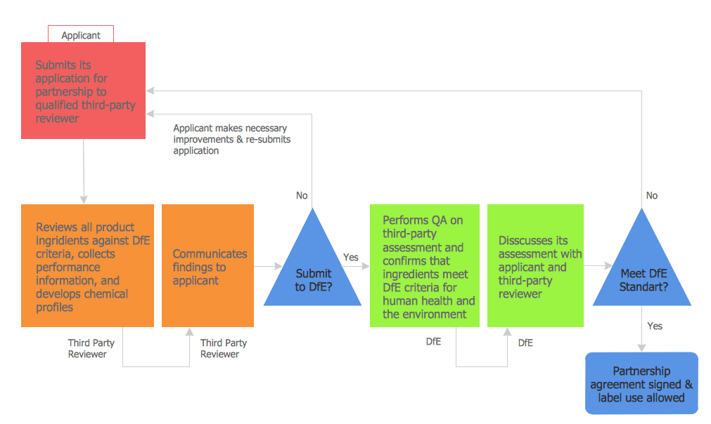
Organigramme du processus d'approbation

Pic 3. Organigramme du processus d'approbation

Cet organigramme a été créé en utilisant les organigrammes de ConceptDraw DIAGRAM. Il montre un schéma de type « les étapes vers un partenariat ».

Les principaux symboles ont été utilisés pour ce schéma.

Les questions exigeant des réponses oui/non, il est nécessaire de prendre la décision qui permettra de déterminer l'étape suivante.

Utilisez la schématisation ConceptDraw DIAGRAM et un logiciel de dessin vectoriel avec des modèles d'organigrammes pour concevoir vos propres diagrammes d'aspect professionnel, rapide et facile.
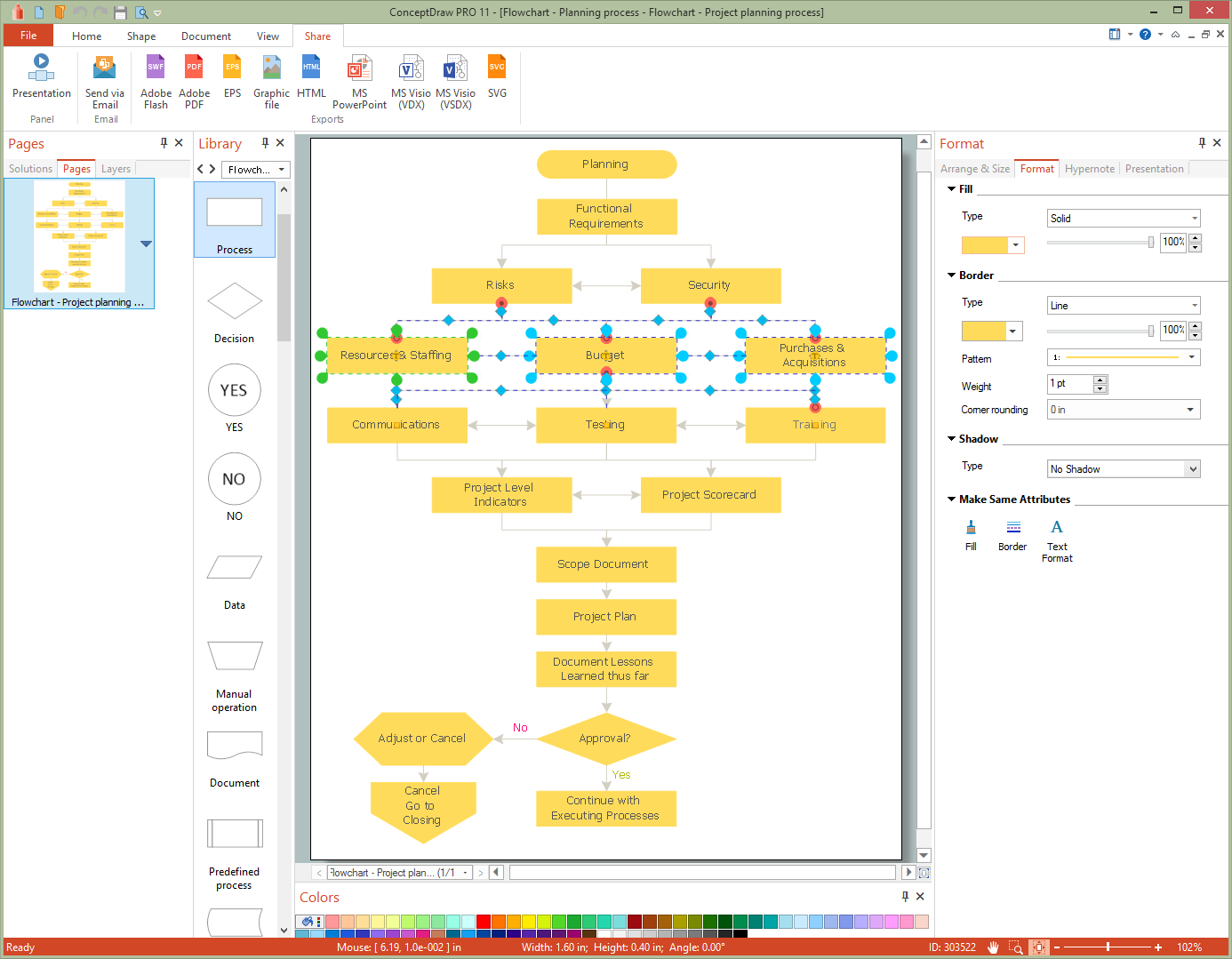
Conception d'organigramme

Conception d'organigramme

Pic 4. Concevez votre propre organigramme d'aspect professionnel (Macintosh® and Microsoft®)

Tous les documents source sont un vecteur de documents graphiques. Ils sont disponibles pour l'examen, à la modification, ou de conversion d'une variété de formats (fichier PDF, MS PowerPoint, MS Visio, et de nombreux autres formats graphiques) à partir du Navigateur de solutions. Les Diagrammes sont disponibles pour les utilisateurs des versions de ConceptDraw DIAGRAM.12 ou ultérieures.


FIVE RELATED HOW TO's:
A database is a data collection, structured into some conceptual model. Two most common approaches of developing data models are UML diagrams and ER-model diagrams. There are several notations of entity-relationship diagram symbols and their meaning is slightly different. Crow’s Foot notation is quite descriptive and easy to understand, meanwhile, the Chen notation is great for conceptual modeling. An entity relationship diagrams look very simple to a flowcharts. The main difference is the symbols provided by specific ERD notations. There are several models applied in entity-relationship diagrams: conceptual, logical and physical. Creating an entity relationship diagram requires using a specific notation. There are five main components of common ERD notations: Entities, Actions, Attributes, Cardinality and Connections. The two of notations most widely used for creating ERD are Chen notation and Crow foot notation. By the way, the Crow foot notation originates from the Chen notation - it is an adapted version of the Chen notation.ERD Symbols and Meanings
Picture: ERD Symbols and Meanings
Related Solution:
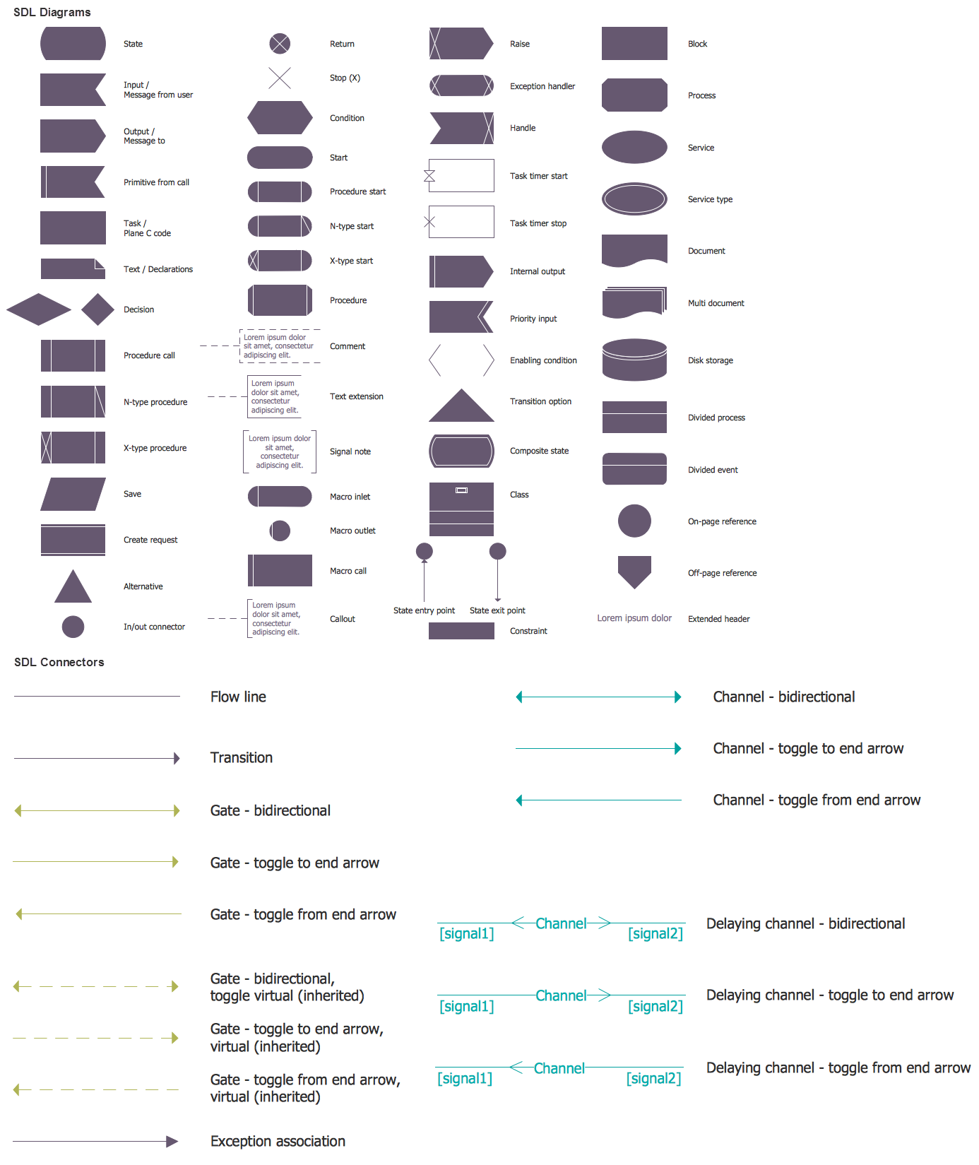
Desbloquee el lenguaje de los diagramas de flujo con nuestra guía de símbolos de diagramas de flujo. 🔸 Todo lo que necesita saber sobre los conceptos básicos del diagrama de flujo, desde ✔️ puntos de decisión hasta ✔️ pasos del proceso, explore el significado detrás de cada símbolo y domine el arte de crear representaciones visuales claras y efectivas de sus procesos.Symboles Organigramme
Picture: Symboles Organigramme
Related Solution:
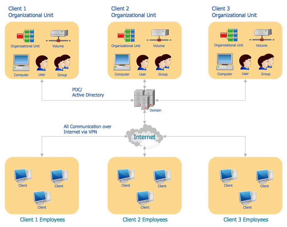
The PERT Chart is constructed as part of the process in creating a schedule of corrective actions. The PERT Chart shows the logical connections and consequence of tasks to be performed. It displays the time period for problem solving and the implementation of all activities through the critical path. ConceptDraw Office suite is a software for corrective actions planning.CORRECTIVE ACTIONS PLANNING. PERT Chart *
Picture: CORRECTIVE ACTIONS PLANNING. PERT Chart
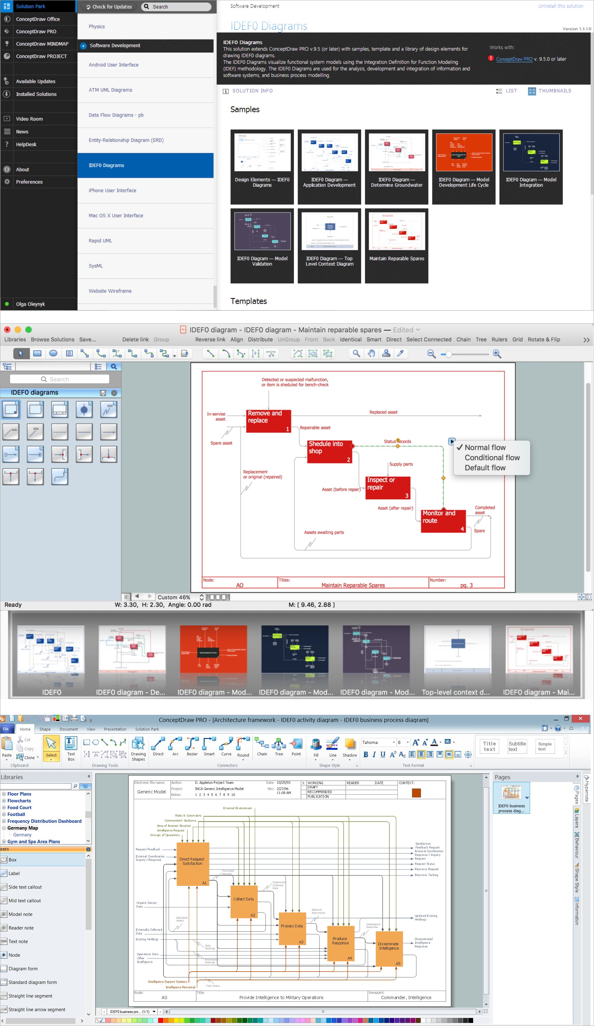
If you ever wanted to try any diagramming tools except of Visio, but were afraid to lose existing documents, there’s good news for you. One of the most striking features of ConceptDraw DIAGRAM is it’s perfect compatibility with MS Visio, which guarantees that you won’t depend on operating system anymore, because another ConceptDraw DIAGRAM feature is that it’s cross-platform tool. Don’t waste your time looking for other options, you’ve found the solution already! Business professionals often utilize the MS Visio as a common tool for making various issues on business visualization. MS Visio is a strong software with good capacity to maintain complex business solutions. But there is no MS Visio for Apple OS X. This is a large invocation, and one would be pleased to recognize that ConceptDraw DIAGRAM is the ideal alternative to MS Visio. Primarily, because this software works natively on both Windows and Apple OS X platforms. if you have migrated from Windows to Mac, or need to communicate in a cross-platform conditions, you’ll search for MS Visio replacer. ConceptDraw DIAGRAM is the exclusive professional business diagramming application that runs on both Windows and Apple OS X. The opportunity exchange files between PC and Mac, as well as between ConceptDraw DIAGRAM and Visio is the significant advantage that permits you to display and to collaborate business information in effortless and cost-effective way.ConceptDraw DIAGRAM Compatibility with MS Visio *
Picture: ConceptDraw DIAGRAM Compatibility with MS Visio
Structured-systems analysis and design method uses data flow diagrams to represent the process of data flowing through a system. Talking about this might be useless without a proper example of DFD for online store (Data Flow Diagram). This DFD example shows all the distinctness that a diagram can bring into a scattered data structure. Data flow diagrams are used to show how data is processed within some business processes. Making DFD is a common practice for business process modeling and analysis. This diagram represents the online store business flow. It describes inputs and outputs within online selling process and depicts the interactions between its participants. This DF diagram can be used by system analysts to create an overview of a business, to study and discover its inherent strengths and weak points.Example of DFD for Online Store
Picture: Example of DFD for Online Store (Data Flow Diagram)
Related Solution:
ConceptDraw
DIAGRAM 18