This pinout diagram example showing a VGA connector (as viewed from the socket) was redesigned from the Wikimedia Commons file: DE15 Connector Pinout.svg. [commons.wikimedia.org/ wiki/ File:DE15_ Connector_ Pinout.svg]
"A Video Graphics Array (VGA) connector is a three-row 15-pin DE-15 connector. The 15-pin VGA connector is found on many video cards, computer monitors, and high definition television sets. On laptop computers or other small devices, a mini-VGA port is sometimes used in place of the full-sized VGA connector.
DE-15 is also conventionally called RGB connector, D-sub 15, mini sub D15, mini D15, DB-15, HDB-15, HD-15 or HD15 (High Density, to distinguish it from the older and less flexible DE-9 connector used on some older VGA cards, which has the same shell size but only two rows of pins).
VGA connectors and cables carry analog component RGBHV (red, green, blue, horizontal sync, vertical sync) video signals, and VESA Display Data Channel (VESA DDC) data. In the original version of DE-15 pinout, one pin was keyed by plugging the female connector hole; this prevented non-VGA 15 pin cables from being plugged into a VGA socket. Four pins carried Monitor ID bits which were rarely used; VESA DDC redefined some of these pins and replaced the key pin with +5 V DC power supply.
The VGA interface is not engineered to be hotpluggable (so that the user can connect or disconnect the output device while the host is running), although in practice this can be done and usually does not cause damage to the hardware or other problems. However, nothing in the design ensures that the ground pins make a connection first and break last, so hotplugging may introduce surges in signal lines which may or may not be adequately protected against. Also, depending on the hardware and software, detecting a monitor being connected might not work properly in all cases." [VGA connector. Wikipedia]
The pinout diagram example "VGA connector pinout" was created using the ConceptDraw PRO diagramming and vector drawing software extended with the Audio and Video Connectors solution from the Engineering area of ConceptDraw Solution Park.
VGA connector pinout

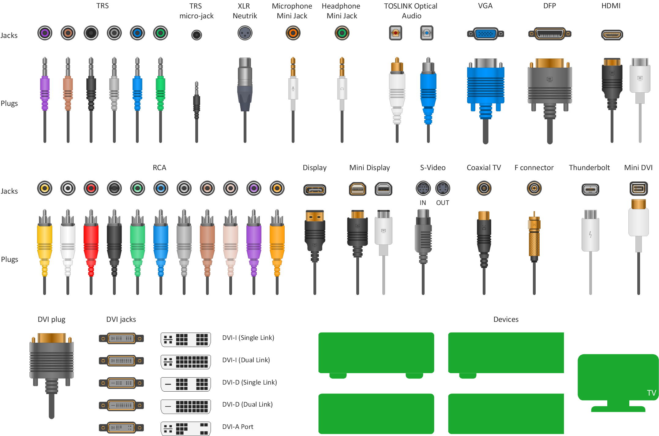
 Audio and Video Connectors
The Audio and Video Connectors solution contains a set of video connectors, audio connectors and s video connection; you will also find pre-designed objects, libraries, templates, and samples, allowing quick and easy diagramming of various configurations
This AV connector pinout diagram example was redesigned from the file: DVI pinout.svg. [en.wikipedia.org/ wiki/ File:DVI_ pinout.svg]
"In electronics, a pinout (sometimes written "pin-out") is a cross-reference between the contacts, or pins, of an electrical connector or electronic component, and their functions. ...
The functions of contacts in electrical connectors, be they power- or signaling-related, must be specified in order for connectors to be interchangeable. When connected, each contact of a connector must mate with the contact on the other connector that has the same function. If contacts of disparate functions are allowed to make contact, the connection may fail and damage may result. Therefore, pinouts are a vital reference when building and testing connectors, cables, and adapters." [Pinout. Wikipedia]
The example "DVI pinout diagram" was created using the ConceptDraw PRO diagramming and vector drawing software extended with the Audio and Video Connectors solution from the Engineering area of ConceptDraw Solution Park.
A female DVI-I socket from the front

Network wiring cable. Computer and Network Examples

This example was created in ConceptDraw DIAGRAM using the Computer and Networks solution from the Computer and Networks area of ConceptDraw Solution Park.

Electrical Symbols — Terminals and Connectors

26 libraries of the Electrical Engineering Solution of ConceptDraw DIAGRAM make your electrical diagramming simple, efficient, and effective. You can simply and quickly drop the ready-to-use objects from libraries into your document to create the electrical diagram.
Network diagrams with ConceptDraw DIAGRAM

Network diagrams are divided into Physical Network Diagrams and Logical Network Diagrams.
Network diagram is an indispensable tool for network administrators and engineers at development of new networks and management of existing networks.
Network Diagram Software. LAN Network Diagrams. Physical Office Network Diagrams

Local area network (LAN). Computer and Network Examples
 diagram")
ConceptDraw - Perfect Network Diagramming Software with examples of LAN Diagrams. ConceptDraw Network Diagram is ideal for network engineers and network designers who need to draw Local Area Network diagrams.
This AV connector pinout diagram example was redesigned from the Wikipedia file: DVI Connector Types.svg.
[en.wikipedia.org/ wiki/ File:DVI_ Connector_ Types.svg]
"Digital Visual Interface (DVI) is a video display interface developed by the Digital Display Working Group (DDWG). The digital interface is used to connect a video source to a display device, such as a computer monitor. It was developed with the intention of creating an industry standard for the transfer of digital video content.
The interface is designed to transmit uncompressed digital video and can be configured to support multiple modes such as DVI-D (digital only), DVI-A (analog only), or DVI-I (digital and analog). Featuring support for analog connections, the DVI specification is compatible with the VGA interface. This compatibility, along with other advantages, led to its widespread acceptance over competing digital display standards Plug and Display (P&D) and Digital Flat Panel (DFP). Although DVI is predominantly associated with computers, it is sometimes used in other consumer electronics such as television sets, video game consoles and DVD players." [Digital Visual Interface. Wikipedia]
The example "DVI connector types" was created using the ConceptDraw PRO diagramming and vector drawing software extended with the Audio and Video Connectors solution from the Engineering area of ConceptDraw Solution Park.
Male DVI connector pins (view of plug)
-dvi-connector-types.png--diagram-flowchart-example.png)
Standard Universal Audio & Video Connection Types
- Vga Connector Diagram
- DVI pinout diagram | VGA connector pinout | Wiring Diagrams with ...
- VGA connector pinout | 15 Pin Vga Cable Wiring Diagram
- Vga Cable Wiring Diagram 15 Pin
- VGA connector pinout | Electrical Symbols, Electrical Diagram ...
- DVI pinout diagram | Av To Vga Cable Line Diagram
- Audio Visual Connectors Types | Vga To Rca Cable Pinout Diagram
- DVI pinout diagram | DVI connector types | Www Diyagram Av To Vga
- VGA connector pinout | Terminals and connectors - Vector stencils ...
- Vga Pinout Diagram
- ERD | Entity Relationship Diagrams, ERD Software for Mac and Win
- Flowchart | Basic Flowchart Symbols and Meaning
- Flowchart | Flowchart Design - Symbols, Shapes, Stencils and Icons
- Flowchart | Flow Chart Symbols
- Electrical | Electrical Drawing - Wiring and Circuits Schematics
- Flowchart | Common Flowchart Symbols
- Flowchart | Common Flowchart Symbols