Data Flow Diagram Symbols. DFD Library

Structured Systems Analysis and Design Method (SSADM) with ConceptDraw PRO

Geo Map - Australia

Basic Flowchart Symbols and Meaning


Entity Relationship Diagram Symbols

ERD symbols used for professional ERD drawing are collected in libraries from the Entity-Relationship Diagram (ERD) solution for ConceptDraw PRO.
Entity Relationship Diagram Software Engineering

Professional ERD drawing is an essential software engineering method for database modeling. ConceptDraw PRO as a powerful Entity Relationship Diagram Software Engineering offers the tools of Entity-Relationship Diagram (ERD) solution from Software Development area of ConceptDraw Solution Park.
UML Sample Project

Horizontal Orgchart
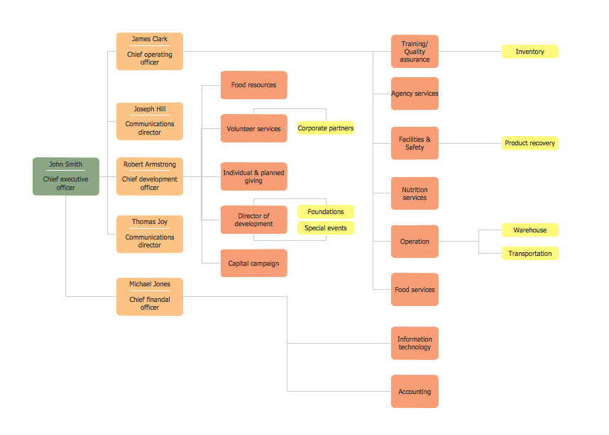
This sample was created in ConceptDraw PRO diagramming and vector drawing software using the Organizational Charts Solution from the Management area of ConceptDraw Solution Park.
Flow chart Example. Warehouse Flowchart

Standard warehousing process flow diagram and standard workflow diagram used for process identification for further evaluating effectiveness and profitability of overall business process. Use the ConceptDraw PRO diagramming and vector drawing software extended with the Flowcharts solution from the Diagrams area of ConceptDraw Solution Park to design your own workflow diagrams, process flow diagram and flow charts. Need to use Process Flow Diagram for designing Warehouse packages flow.

Horizontal Org Flow Chart

The Organizational Chart is a diagram that shows the structure of the organization, different levels of management, hierarchy and the relationships of the organization parts.
- What Is Dfd In S E And Examples
- Dfd In Se
- ConceptDraw PRO DFD Software | Example Of Dfd In Se
- Data Flow Diagram In Se 1
- Data Flow Diagrams ( DFD ) | Dfd Examples In Se Pdf File
- Data Flow Diagrams ( DFD ) | Process Oriented Design Gane Sarson ...
- Concept Used In Constructing Data Flow Diagram
- Library Management Ppt Dfd Diagram In Se
- ConceptDraw PRO DFD Software | Process Oriented Design Gane ...
- Dfd Diagram For Se Project On Photo Editor
- ERD | Entity Relationship Diagrams, ERD Software for Mac and Win
- Flowchart | Basic Flowchart Symbols and Meaning
- Flowchart | Flowchart Design - Symbols, Shapes, Stencils and Icons
- Flowchart | Flow Chart Symbols
- Electrical | Electrical Drawing - Wiring and Circuits Schematics
- Flowchart | Common Flowchart Symbols
- Flowchart | Common Flowchart Symbols