Context Diagram Template

This template shows the Context Diagram. It was created in ConceptDraw DIAGRAM diagramming and vector drawing software using the Block Diagrams Solution from the “Diagrams” area of ConceptDraw Solution Park. The context diagram graphically identifies the system. external factors, and relations between them. It’s a high level view of the system. The context diagrams are widely used in software engineering and systems engineering for designing the systems that process the information.
ER Diagram Tool

ORM Diagram

Booch OOD Diagram

Basic Flowchart Symbols and Meaning


Network Diagram Software. LAN Network Diagrams. Physical Office Network Diagrams


Functional Block Diagram

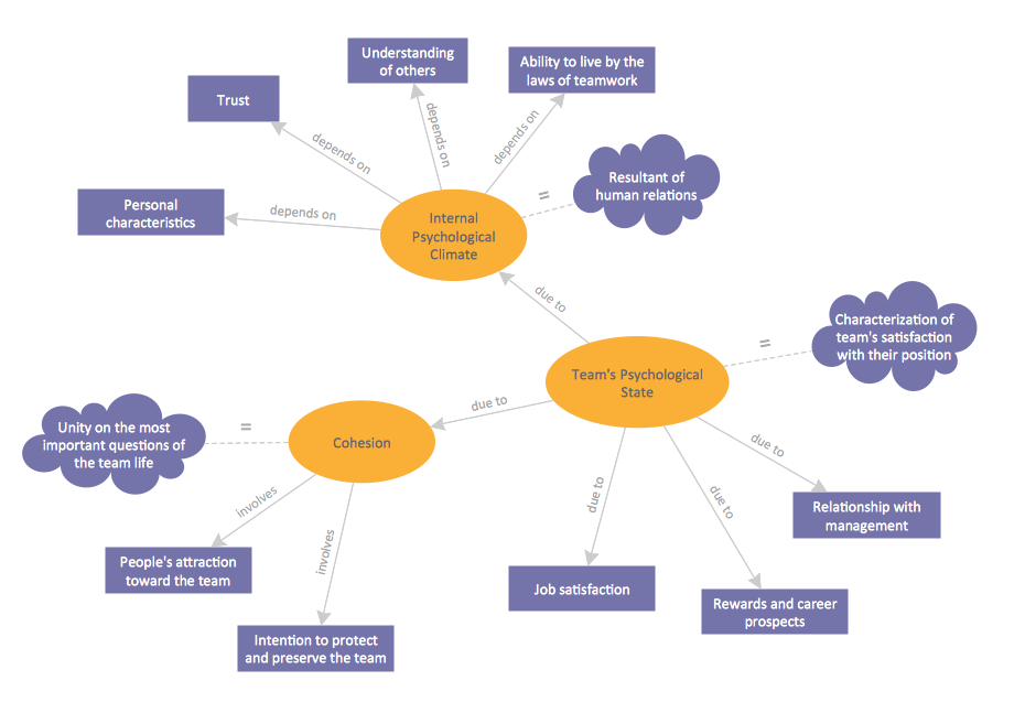
Concept Map
Electrical Diagram

UML Class Diagram Notation

- Visio Files and ConceptDraw | Visio Data Flow Diagram From Xml
- Diagram Viewer Online Help | How to Convert MS Visio® 2003 ...
- ER Diagram Of Online Video Streaming
- Diagram Viewer Online Help | How to Convert ConceptDraw PRO ...
- Xml Block Diagram
- Edit Visio Online
- Download Data Flow Diagram Vsd
- Xml Building Block With Diagram
- Diagram Viewer Online Help | Visio Files and ConceptDraw | MS ...