This sport field plan sample was designed on the base of the Wikipedia file: VolleyballCourt.svg. [en.wikipedia.org/ wiki/ File:VolleyballCourt.svg]
This file is licensed under the Creative Commons Attribution-Share Alike 3.0 Unported license. [creativecommons.org/ licenses/ by-sa/ 3.0/ deed.en]
"Volleyball is a team sport in which two teams of six players are separated by a net. Each team tries to score points by grounding a ball on the other team's court under organized rules. It has been a part of the official program of the Summer Olympic Games since 1964. ...
The court dimensions.
A volleyball court is 18 m (59 ft) long and 9 m (29.5 ft) wide, divided into 9 m × 9 m halves by a one-meter (40-inch) wide net. The top of the net is 2.43 m (8 ft 0 in) above the center of the court for men's competition, and 2.24 m (7 ft 4 in) for women's competition, varied for veterans and junior competitions.
The minimum height clearance for indoor volleyball courts is 7 m (23 ft), although a clearance of 8 m (26 ft) is recommended.
A line 3 m (9.84 ft) from and parallel to the net is considered the "attack line". This "3 meter" (or "10-foot") line divides the court into "back row" and "front row" areas (also back court and front court). These are in turn divided into 3 areas each: these are numbered as follows, starting from area "1", which is the position of the serving player.
After a team gains the serve (also known as siding out), its members must rotate in a clockwise direction, with the player previously in area "2" moving to area "1" and so on, with the player from area "1" moving to area "6".
The team courts are surrounded by an area called the free zone which is a minimum of 3 meters wide and which the players may enter and play within after the service of the ball. All lines denoting the boundaries of the team court and the attack zone are drawn or painted within the dimensions of the area and are therefore a part of the court or zone. If a ball comes in contact with the line, the ball is considered to be "in". An antenna is placed on each side of the net perpendicular to the sideline and is a vertical extension of the side boundary of the court. A ball passing over the net must pass completely between the antennae (or their theoretical extensions to the ceiling) without contacting them." [Volleyball. Wikipedia]
The sport field plan example "Volleyball court dimensions" was created using the ConceptDraw PRO diagramming and vector drawing software extended with the Sport Field Plans solution from the Building Plans area of ConceptDraw Solution Park.
Sport field plan

Basketball Court Dimensions

This example of cloud computing system architecture diagram was created on the base of picture in the post "Sending Windows 8 Push Notifications using Windows Azure Mobile Services" from the Nick Harris .NET blog.
"The goal of Windows Azure Mobile Services is to make it incredibly easy for developers to add a cloud backend to their client apps be it a Windows 8, Windows Phone, iOS or Android application. ... Mobile Services today provides:
- Structured Storage
- Server Logic ...
- Auth ...
- Push Notifications ...
- Common tenants of Windows Azure Services
- Scale ...
- Diagnostics ...
- Logging ...
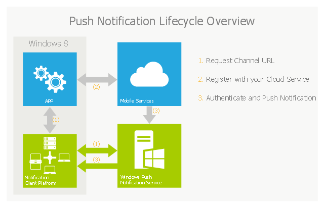
What are Push Notifications?
The Windows Push Notification Services (WNS) enables you to send toast, tile, badge and raw notifications from the cloud to your Windows Store applications even when your app is not running. Push notifications are ideal for scenarios when you need to target a specific user with personalized content.
The following diagram depicts the general Lifecycle of a push notifications via the Windows Azure Notification Service (WNS). We’ll walk through the steps shortly but before doing so I thought it would be important to call out that as a developer implementing a push notification scenario all you need to do is implement those interactions in grey and the applications/ services in blue." [nickharris.net/ index.php/ 2012/ 10/ 04/ blog-series-sending-windows-8-push-notifications-using-windows-azure-mobile-services/ ]
The diagram example "Push Notification Lifecycle Overview" was created using ConceptDraw PRO diagramming and vector drawing software extended with the Azure Architecture solution from the Computer and Networks area of ConceptDraw Solution Park.
"The goal of Windows Azure Mobile Services is to make it incredibly easy for developers to add a cloud backend to their client apps be it a Windows 8, Windows Phone, iOS or Android application. ... Mobile Services today provides:
- Structured Storage
- Server Logic ...
- Auth ...
- Push Notifications ...
- Common tenants of Windows Azure Services
- Scale ...
- Diagnostics ...
- Logging ...
What are Push Notifications?
The Windows Push Notification Services (WNS) enables you to send toast, tile, badge and raw notifications from the cloud to your Windows Store applications even when your app is not running. Push notifications are ideal for scenarios when you need to target a specific user with personalized content.
The following diagram depicts the general Lifecycle of a push notifications via the Windows Azure Notification Service (WNS). We’ll walk through the steps shortly but before doing so I thought it would be important to call out that as a developer implementing a push notification scenario all you need to do is implement those interactions in grey and the applications/ services in blue." [nickharris.net/ index.php/ 2012/ 10/ 04/ blog-series-sending-windows-8-push-notifications-using-windows-azure-mobile-services/ ]
The diagram example "Push Notification Lifecycle Overview" was created using ConceptDraw PRO diagramming and vector drawing software extended with the Azure Architecture solution from the Computer and Networks area of ConceptDraw Solution Park.
Cloud computing system architecture diagram
Azure Management
 Project Exchange
This solution extends ConceptDraw PROJECT and ConceptDraw MINDMAP software with the ability to import and export project data.
 Network Layout Floor Plans
Network Layout Floor Plans solution extends ConceptDraw DIAGRAM software functionality with powerful tools for quick and efficient documentation the network equipment and displaying its location on the professionally designed Network Layout Floor Plans. Never before creation of Network Layout Floor Plans, Network Communication Plans, Network Topologies Plans and Network Topology Maps was not so easy, convenient and fast as with predesigned templates, samples, examples and comprehensive set of vector design elements included to the Network Layout Floor Plans solution. All listed types of plans will be a good support for the future correct cabling and installation of network equipment.
Metropolitan area networks (MAN). Computer and Network Examples
. Computer and Network Examples")

HelpDesk
How to Make a Web Page from Infographics

This Azure cloud architecture pattern diagram template was created on the base of figure in the article "Competing Consumers Pattern" from the Microsoft Developer Network (MSDN) website.
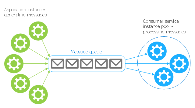
"Competing Consumers Pattern.
Enable multiple concurrent consumers to process messages received on the same messaging channel. This pattern enables a system to process multiple messages concurrently to optimize throughput, to improve scalability and availability, and to balance the workload. ...
An application running in the cloud may be expected to handle a large number of requests. Rather than process each request synchronously, a common technique is for the application to pass them through a messaging system to another service (a consumer service) that handles them asynchronously. This strategy helps to ensure that the business logic in the application is not blocked while the requests are being processed. ...
Use a message queue to implement the communication channel between the application and the instances of the consumer service. The application posts requests in the form of messages to the queue, and the consumer service instances receive messages from the queue and process them. This approach enables the same pool of consumer service instances to handle messages from any instance of the application." [msdn.microsoft.com/ ru-RU/ library/ dn568101.aspx]
The Azure cloud system architecture diagram template "Competing consumers pattern" for the ConceptDraw PRO diagramming and vector drawing software is included in the Azure Architecture solutin from the Computer and Networks area of ConceptDraw Solution Park.
Cloud computing system architecture diagram template
HelpDesk
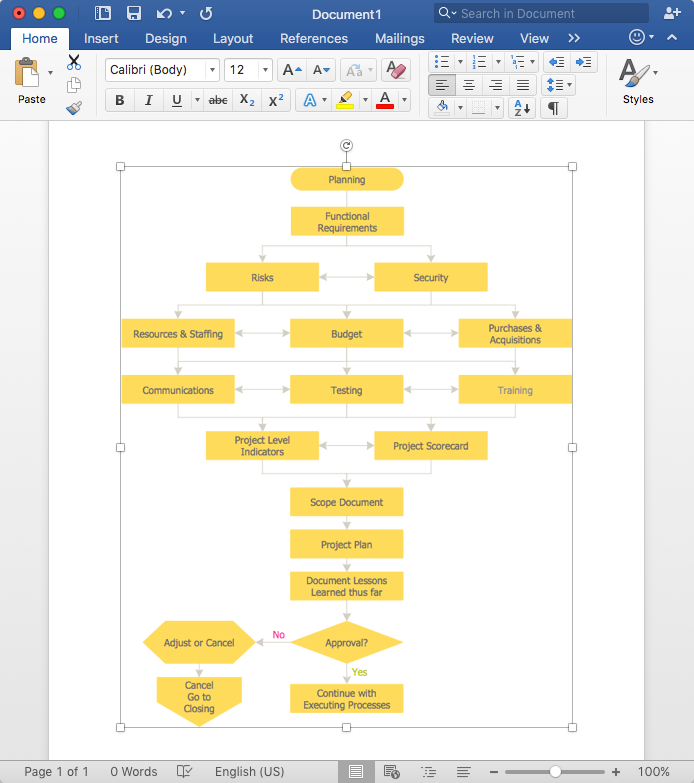
How to Add a Flowchart to MS Word Document
Personal area (PAN) networks. Computer and Network Examples
 networks")
This cloud computing system architecture diagram example was created on the base of the picture in the post "Windows Azure Solution Cookbook" from the Clint Edmonson's blog notsotrivial.net.
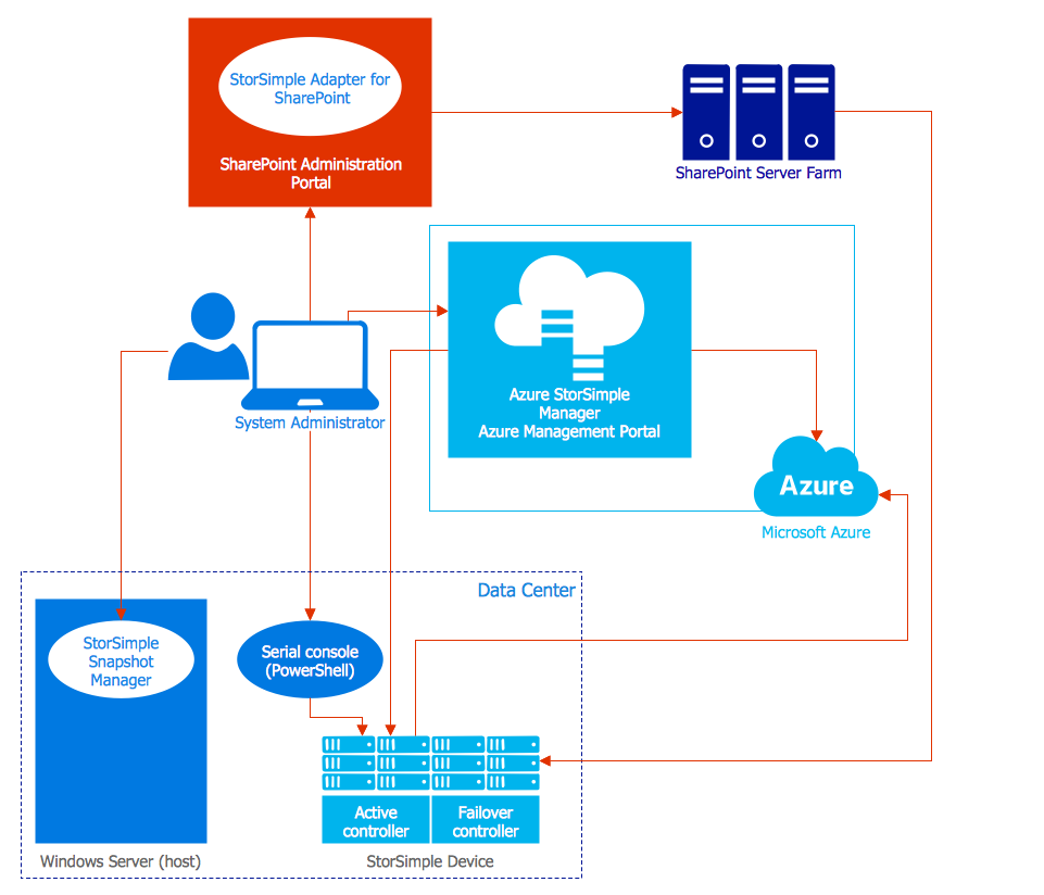
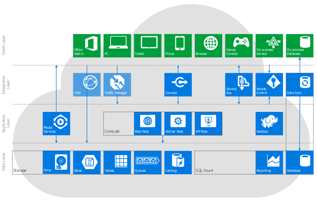
"The diagram you see ... is designed to provide a layered architectural overview of the developer and infrastructure services currently available in Windows Azure." [notsotrivial.net/ blog/ post/ 2012/ 07/ 02/ Windows-Azure-Solution-Cookbook.aspx]
The diagram example "Microsoft Azure reference architecture" was created using ConceptDraw PRO diagramming and vector drawing software extended with the Azure Architecture solution from the Computer and Networks area of ConceptDraw Solution Park.
Cloud computing system architecture diagram
 Cisco Network Diagrams
Cisco Network Diagrams solution extends ConceptDraw DIAGRAM with the best characteristics of network diagramming software. Included samples, templates and libraries of built-in standardized vector Cisco network icons and Cisco symbols of computers, network devices, network appliances and other Cisco network equipment will help network engineers, network designers, network and system administrators, as well as other IT professionals and corporate IT departments to diagram efficiently the network infrastructure, to visualize computer networks topologies, to design Cisco computer networks, and to create professional-looking Cisco Computer network diagrams, Cisco network designs and schematics, Network maps, and Network topology diagrams in minutes.
 Rack Diagrams
The Rack Diagrams solution, including a vector stencil library, a collection of samples and a quick-start template, can be useful for all who deal with computer networks. Choosing any of the 54 library's vector shapes, you can design various types of Rack diagrams or Server rack diagrams visualizing 19" rack mounted computers and servers.
- Cloud Net
- Net Diagram
- Sample Net
- Bus Net Working Diagram
- Net Security
- Volleyball court dimensions | Measurement Of Net And Volleyball
- Pyramid Diagrams | Marketing | Basketball | Net Diagram Of ...
- Communication Net Diagram
- Draw A Simple Net Work Topology
- Net Work Topolagies Diagram
- Soccer | Download Pdf Data Flow Diagram Library System Vb Net
- Broadband Net Diagrams
- Hybrid Lan Net Work
- Net Work Diagram For Process Of Information System
- Net Diagram Of A Triangular Pyramid
- Concept Draw Net
- Hotel Servicing Communication Net
- Network Topologies | Mobile satellite TV network diagram | Ring ...
- Sport Field Plans | Volleyball Net Illustration
- Computer Network Diagrams | Power Point Active Control Asp Net