Fishbone Diagram Design Element
.png)
 Floor Plans
Construction, repair and remodeling of the home, flat, office, or any other building or premise begins with the development of detailed building plan and floor plans. Correct and quick visualization of the building ideas is important for further construction of any building.
Entity Relationship Diagram Software Engineering

ER Diagram for Cloud Computing

Components of ER Diagram

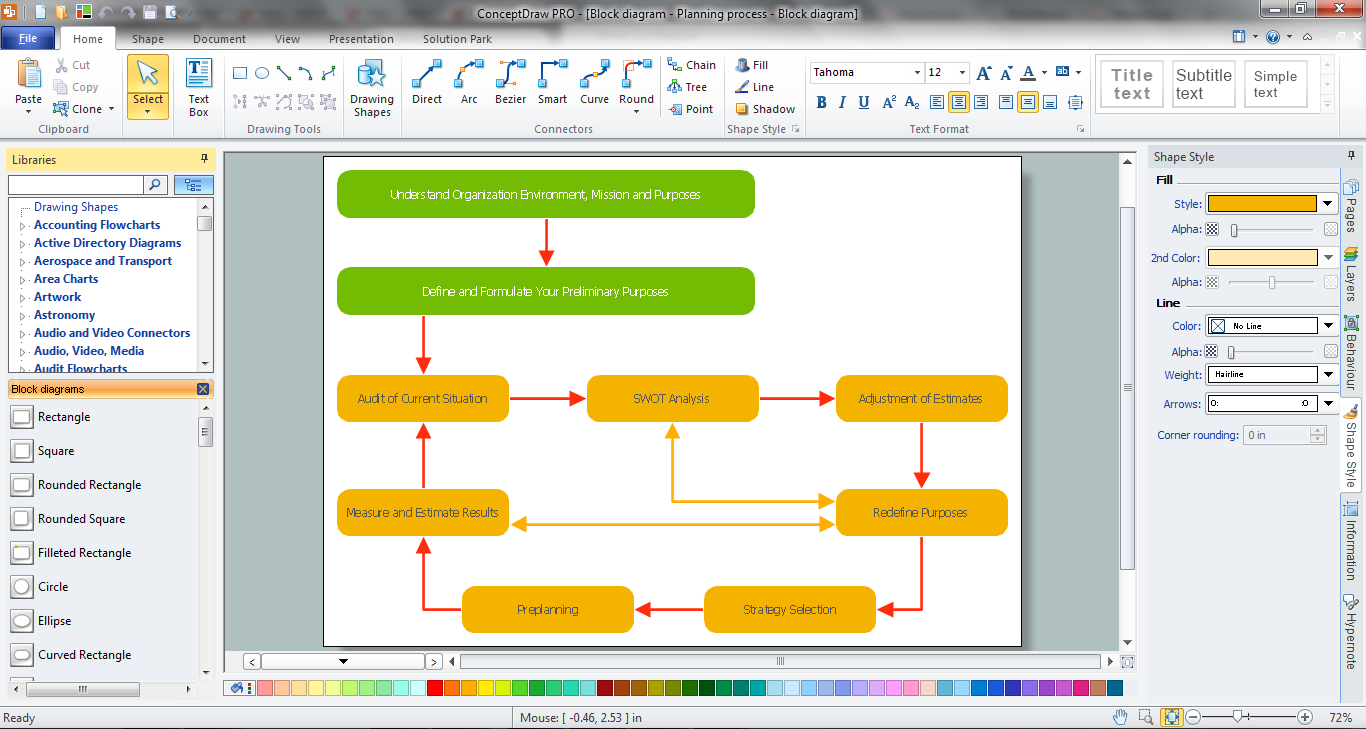
Block Diagram Software
ConceptDraw DIAGRAM Network Diagram Tool


 Fire and Emergency Plans
It's a good idea to have an emergency exit strategy in place for your home or business. ConceptDraw gives you the tools to create your own fire and emergency plan, tailored to your setting.
ER diagram tool for OS X
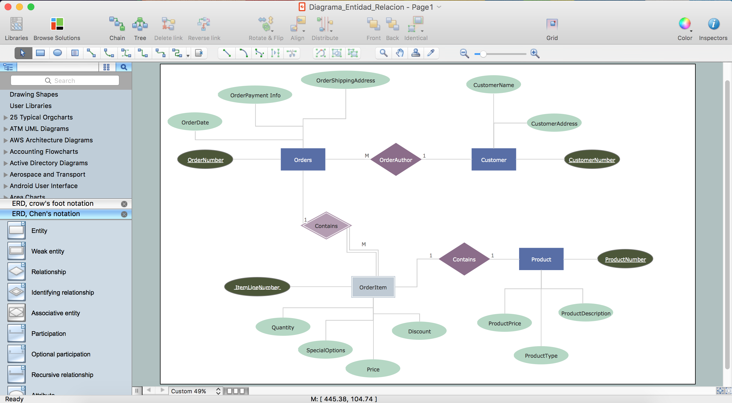
Entity Relationship Diagram Symbols

- Er Diagram Of Collage Pdf
- Er Diagram Of University Management System Pdf
- Warehouse layout floor plan | Commercial Building Layout
- Electrical Building Installation Layout And Wiring Diagram In Pdf
- ERD Symbols and Meanings | Entity Relationship Diagram Symbols ...
- Network Layout | Office Building Networks Design Diagrams Pdf
- Commercial Building Electrical Wiring Plan
- Er Diagram For University Management System Pdf
- 10 Floor Office Building Network Design Pdf
- Data Flow Diagrams (DFD) | Process Flowchart | How to Create a ...