Data Flow Diagram

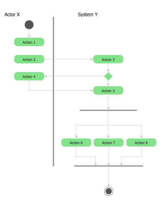
UML 2 4 Process Flow Diagram
UML Flowchart Symbols

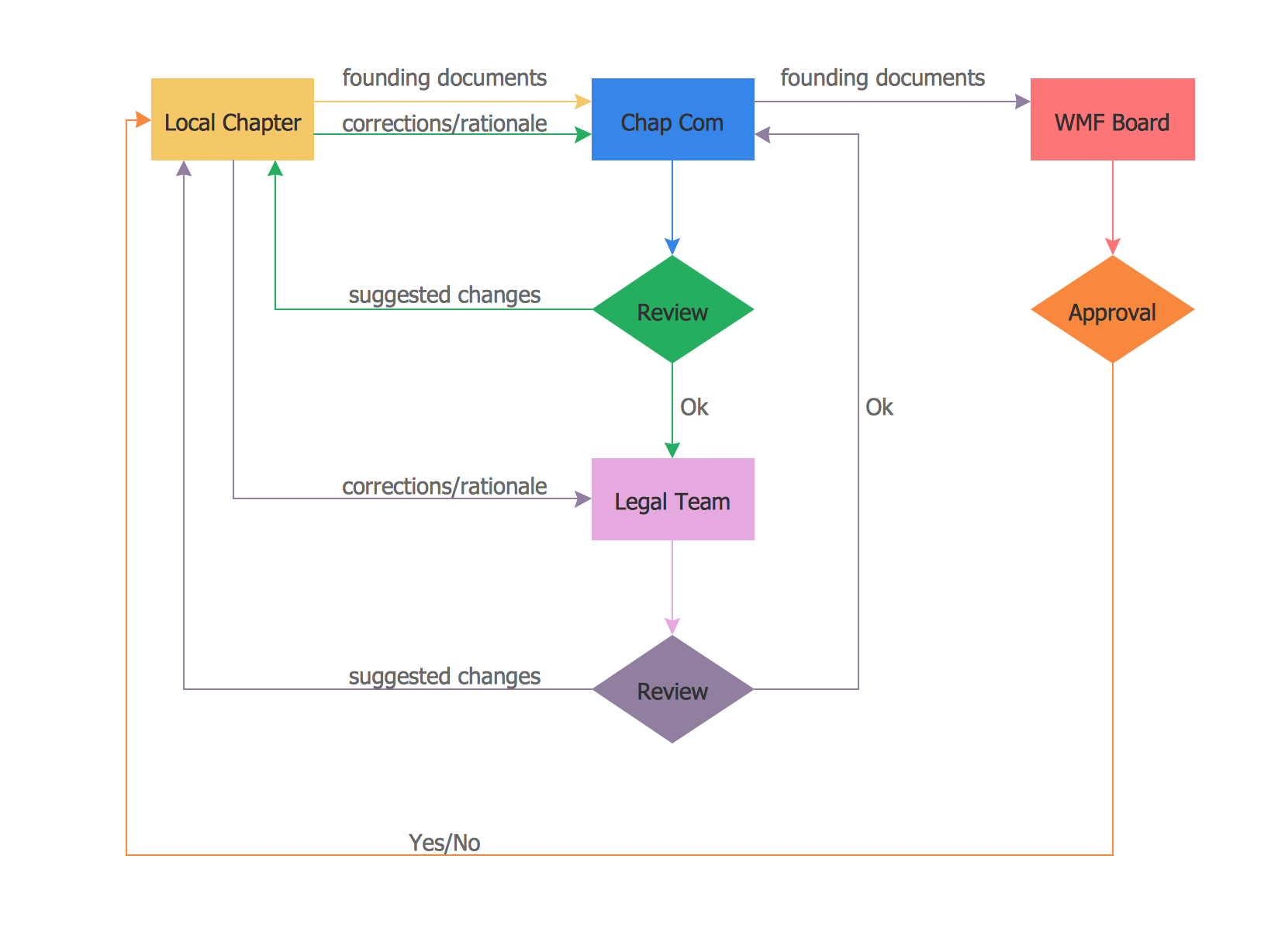
UML Business Process

Flowchart Components

Data Flow Diagrams

Business Process Flow Diagram
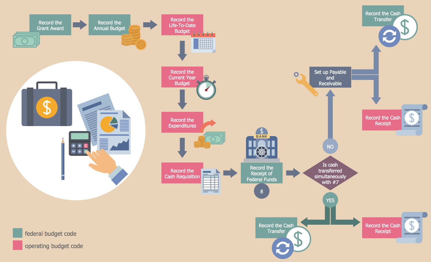
Process Flow Chart Examples
UML Use Case Diagram Example. Registration System

Software Diagram Examples and Templates

- Uml 2 4 Process Flow Diagram
- UML Sample Project | UML 2 4 Process Flow Diagram | UML Use ...
- Taxi Service Data Flow Diagram DFD Example | UML Use Case ...
- Functional Flow Diagram Uml
- Business Process Diagrams | Process Flowchart | Diagramming ...
- UML Business Process | UML Process Diagram Example | Process ...
- Process Flowchart | Technical Flow Chart Example | UML Tool ...
- Swim Lane Diagrams | Swim Lane Flowchart Symbols | Cross ...
- How To Create a MS Visio Business Process Diagram Using ...
- Process Flowchart | UML Use Case Diagram Example Registration ...