UML Deployment Diagram. Design Elements

UML Component Diagram. Design Elements
")

UML Block Diagram

The vector stencils library "Bank UML component diagram" contains 13 shapes for drawing UML component diagrams.
Use it for object-oriented modeling of your bank information system.
"A component is something required to execute a stereotype function. Examples of stereotypes in components include executables, documents, database tables, files, and library files.
Components are wired together by using an assembly connector to connect the required interface of one component with the provided interface of another component. This illustrates the service consumer - service provider relationship between the two components. ...
When using a component diagram to show the internal structure of a component, the provided and required interfaces of the encompassing component can delegate to the corresponding interfaces of the contained components. ...
Symbols.
This may have a visual stereotype in the top right of the rectangle of a small rectangle with two even smaller rectangles jutting out on the left.
The lollipop, a small circle on a stick represents an implemented or provided interface. The socket symbol is a semicircle on a stick that can fit around the lollipop. This socket is a dependency or needed interface." [Component diagram. Wikipedia]
This example of UML component diagram symbols for the ConceptDraw PRO diagramming and vector drawing software is included in the ATM UML Diagrams solution from the Software Development area of ConceptDraw Solution Park.
UML component diagram symbols

UML Class Diagram Notation

UML Composite Structure Diagram. Design Elements

How to create a UML Diagram

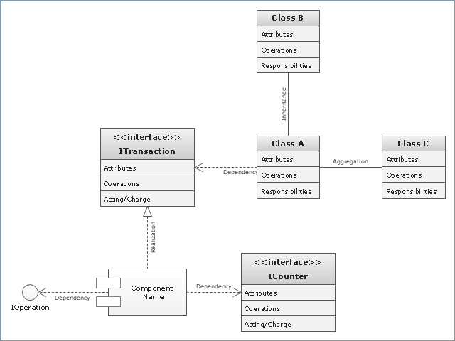
"In software engineering, a class diagram in the Unified Modeling Language (UML) is a type of static structure diagram that describes the structure of a system by showing the system's classes, their attributes, operations (or methods), and the relationships among objects. ...
The class diagram is the main building block of object oriented modelling. It is used both for general conceptual modelling of the systematics of the application, and for detailed modelling translating the models into programming code. Class diagrams can also be used for data modeling. The classes in a class diagram represent both the main objects, interactions in the application and the classes to be programmed." [Class diagram. Wikipedia]
The template "UML class diagram" for the ConceptDraw PRO diagramming and vector drawing software is included in the Rapid UML solution from the Software Development area of ConceptDraw Solution Park.
www.conceptdraw.com/ solution-park/ software-uml
UML class diagram
 ATM UML Diagrams
The ATM UML Diagrams solution lets you create ATM solutions and UML examples. Use ConceptDraw PRO as a UML diagram creator to visualize a banking system.
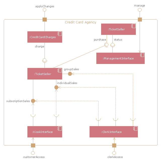
"A credit card is a payment card issued to users as a system of payment. It allows the cardholder to pay for goods and services based on the holder's promise to pay for them. The issuer of the card creates a revolving account and grants a line of credit to the consumer (or the user) from which the user can borrow money for payment to a merchant or as a cash advance to the user." [Credit card. Wikipedia]
The UML component diagram example "Credit card agency" was created using the ConceptDraw PRO diagramming and vector drawing software extended with the Rapid UML solution from the Software Development area of ConceptDraw Solution Park.
The UML component diagram example "Credit card agency" was created using the ConceptDraw PRO diagramming and vector drawing software extended with the Rapid UML solution from the Software Development area of ConceptDraw Solution Park.
UML component diagram
UML Activity Diagram

UML Use Case Diagram. Design Elements
")
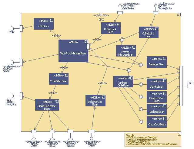
This UML sequence diagram of order processing center (OPC) was created on the base of sequence diagram from the software architecture documentation wiki of the Software Engineering Institute (SEI) of Carnegie Mellon University (CMU).
[wiki.sei.cmu.edu/ sad/ index.php/ Image:OPCRuntimeRefinementView_ PP2.png]
"Order processing is the process or work-flow associated with the picking, packing and delivery of the packed items to a shipping carrier. Order processing is a key element of order fulfillment. Order processing operations or facilities are commonly called "distribution centers"." [Order processing. Wikipedia]
This order processing center UML sequence diagram example was created using the ConceptDraw PRO diagramming and vector drawing software extended with the ATM UML Diagrams solution from the Software Development area of ConceptDraw Solution Park.
Order processing center UML sequence diagram
UML Diagram Types List

How to create your UML Diagram

- Uml Component Diagram
- UML Deployment Diagram Example - ATM System | Design ...
- Collaboration With Class Diagram With Interface In Uml For Simple
- Design elements - Bank UML component diagram | UML ...
- Credit Card Processing System UML Diagram
- Uml Class Diagram Interface Example طراحی
- UML Block Diagram
- Class Diagram Tool | UML Class Diagram Generalization Example ...
- Visio Files and ConceptDraw | UML Diagram Visio | MS Visio Look a ...
- UML Diagrams with ConceptDraw PRO | Software and Database ...
- UML for Bank | ATM UML Diagrams | UML use case diagram ...
- UML Class Diagram Notation
- Design elements - Bank UML profile diagram | Design elements ...
- Uml Deployment Diagram
- Design elements - Bank UML component diagram | UML for Bank ...
- Design elements - Bank UML component diagram | UML Diagram ...
- Design elements - Bank UML component diagram | Design ...
- UML Deployment Diagram Example
- UML Component Diagram Example - Online Shopping | UML ...
- How to create your UML Diagram | Cross-Functional Flowchart ...