"Logical topology, or signal topology, is the arrangement of devices on a computer network and how they communicate with one another. How devices are connected to the network through the actual cables that transmit data, or the physical structure of the network, is called the physical topology. Physical topology defines how the systems are physically connected. It represents the physical layout of the devices on the network. The logical topology defines how the systems communicate across the physical topologies.
Logical topologies are bound to network protocols and describe how data is moved across the network. ...
EXAMPLE : twisted pair Ethernet is a logical bus topology in a physical star topology layout. while IBM's token ring is a logical ring topology, it is physically set up in star topology." [Logical topology. Wikipedia]
This Cisco logical computer network diagram example was created using the ConceptDraw PRO diagramming and vector drawing software extended with the Cisco Network Diagrams solution from the Computer and Networks area of ConceptDraw Solution Park.
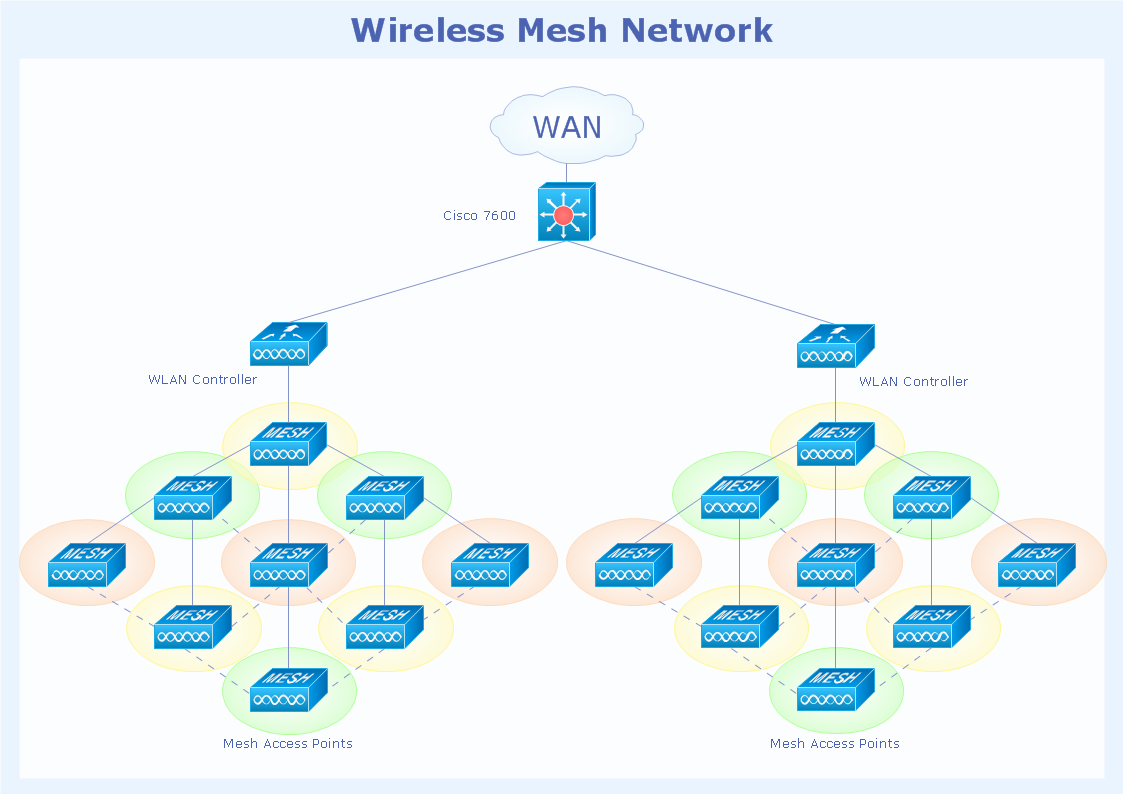
Logical network topology diagram

Bus Network Topology

Cisco Network Topology
Complete Network Topology

Mesh Network Topology Diagram

Star Network Topology


Point to Point Network Topology

Hotel Network Topology Diagram

Local area network (LAN). Computer and Network Examples
 diagram")

 Network Layout Floor Plans
Network Layout Floor Plans solution extends ConceptDraw DIAGRAM software functionality with powerful tools for quick and efficient documentation the network equipment and displaying its location on the professionally designed Network Layout Floor Plans. Never before creation of Network Layout Floor Plans, Network Communication Plans, Network Topologies Plans and Network Topology Maps was not so easy, convenient and fast as with predesigned templates, samples, examples and comprehensive set of vector design elements included to the Network Layout Floor Plans solution. All listed types of plans will be a good support for the future correct cabling and installation of network equipment.
- Physical And Logical Network Layout
- Logical network topology diagram | Diagram Of Ring Topology
- Network Layout | Network Diagram Examples | Design Element ...
- Network Layout Floor Plans | Draw Network Diagram based on ...
- Bus Topology Diagram
- Physical LAN topology diagram | Logical network topology diagram ...
- Logical network topology diagram | Network Diagram Examples ...
- Logical network topology diagram | Physical Topology Diagrams ...
- Diagram Physical Topologies | Physical LAN topology diagram ...
- Wireless access point - Network diagram | Hotel Network Topology ...