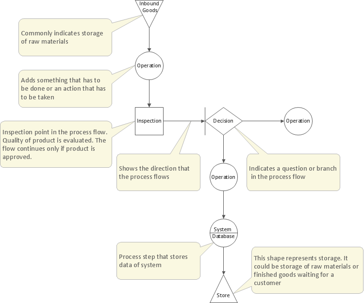
Basic Flowchart Symbols and Meaning


Entity Relationship Diagram Symbols

ERD Symbols and Meanings


Process Flow Chart Symbol

HelpDesk
How to Create Flowchart Using Standard Flowchart Symbols
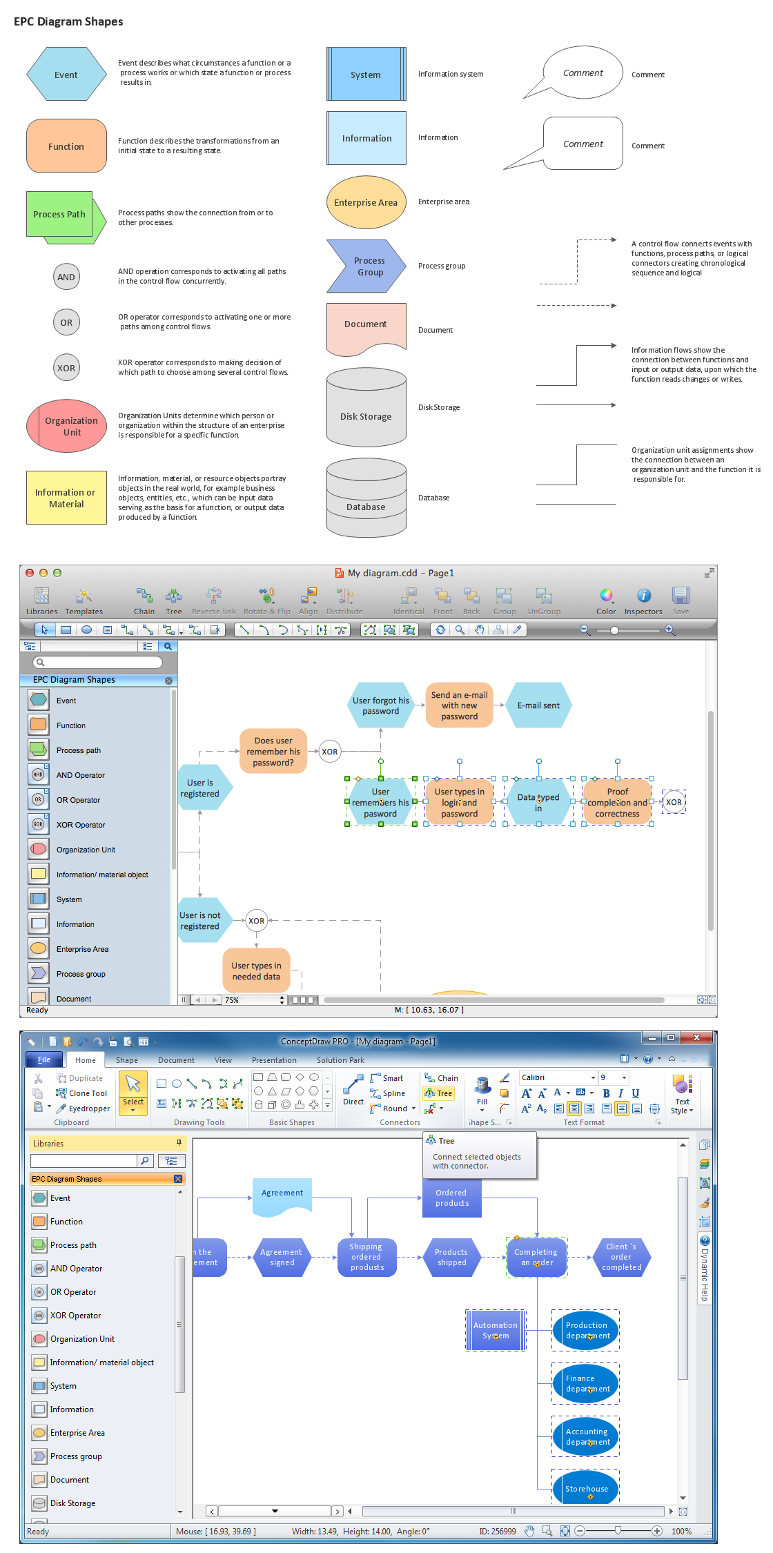
Graphical Symbols to use in EPC diagrams
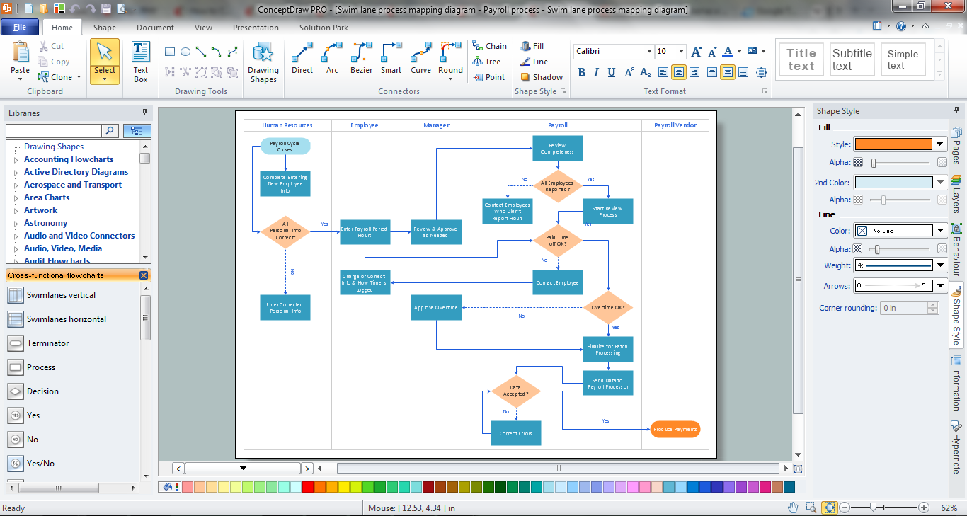
Cross Functional Flowchart
Flow Chart Design - How to Design a Good Flowchart
Management Tools — Total Quality Management
Data Flow Diagram

- The Symbol That Is Represented Using Rectangle In A Flowchart Is
- The Symbol That Is Represented Using Rectangle In Flow Chart Is
- Solving quadratic equation algorithm - Flowchart | Rectangle ...
- The Processing Box Is Represented By Rectangle
- The Symbol That Is Represent Using Rhombus In A Flowchart Is
- How to Create Flowchart Using Standard Flowchart Symbols | The ...
- What Is The Symbol That Is Represented Using Rhombus In A
- In Flowcharts The Symbol Of Rectangle Is Used To Show
- In Flowchart The Symbol Of Rectangle Is Used To Show
- A Processing Step Is Represented In A Flowchart By A Rectangle