 Data Flow Diagrams (DFD)
Data Flow Diagrams solution extends ConceptDraw DIAGRAM software with templates, samples and libraries of vector stencils for drawing the data flow diagrams (DFD).
JSD - Jackson system development

Process Flowchart

IDEF0 Visio

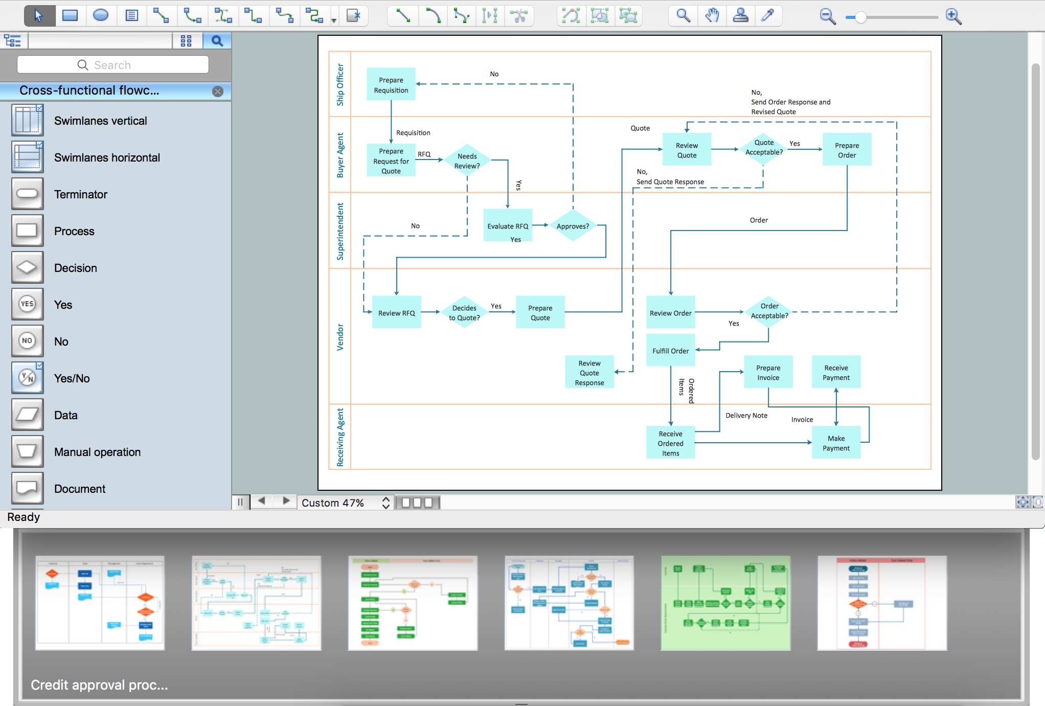
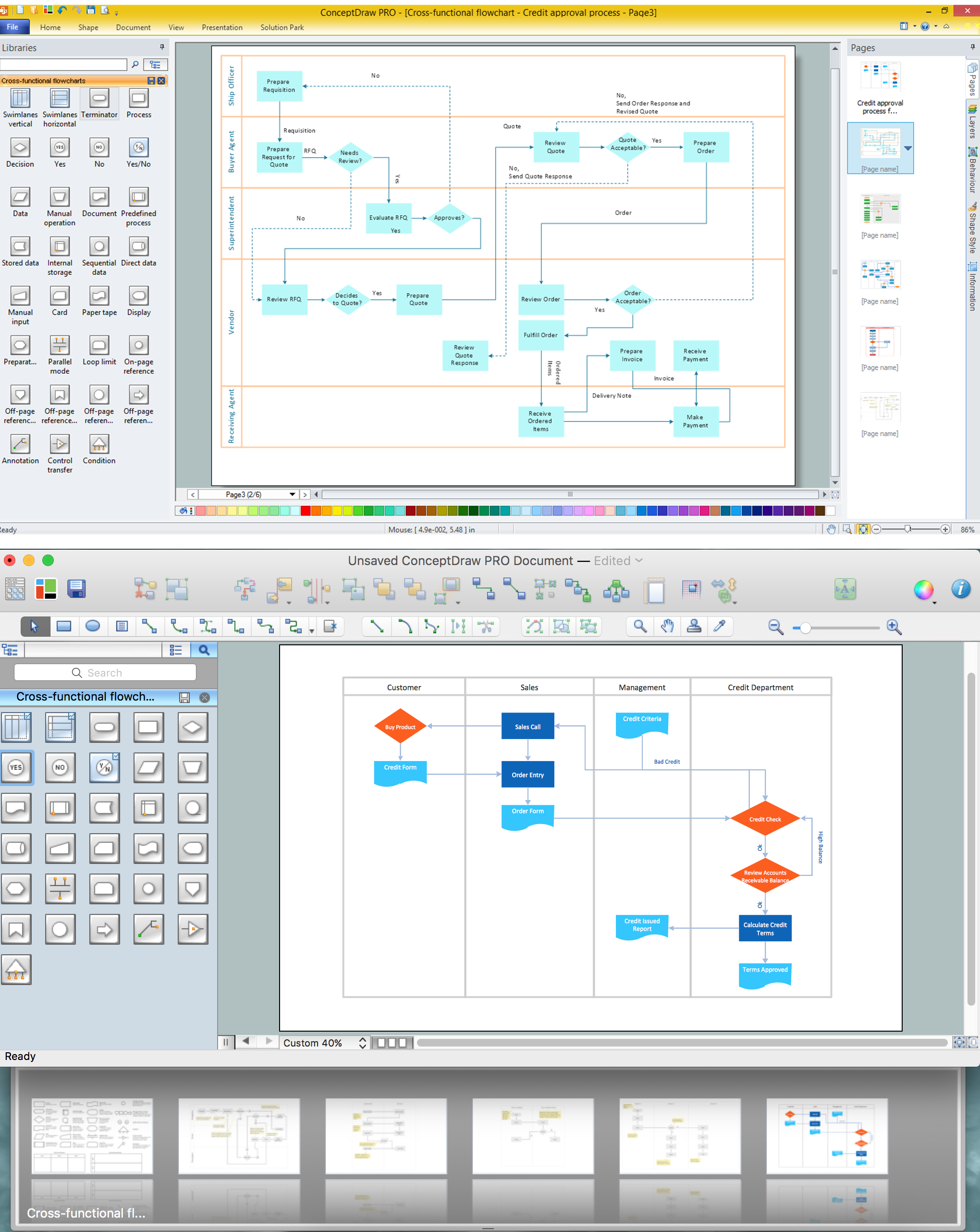
Cross-Functional Flowchart

How To use House Electrical Plan Software


 Event-driven Process Chain Diagrams
Event-driven Process Chain (EPC) Diagram is a type of flowchart widely used for modeling in business engineering and reengineering, business process improvement, and analysis. EPC method was developed within the Architecture of Integrated Information Systems (ARIS) framework.
 Fishbone Diagrams
The Fishbone Diagrams solution extends ConceptDraw DIAGRAM software with the ability to easily draw the Fishbone Diagrams (Ishikawa Diagrams) to clearly see the cause and effect analysis and also problem solving. The vector graphic diagrams produced using this solution can be used in whitepapers, presentations, datasheets, posters, and published technical material.
Introductory Guide to Rapid UML Solution

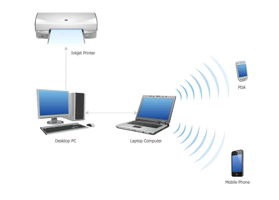
Personal area (PAN) networks. Computer and Network Examples

- System Analysis And Design Tutorial Pdf Free Download
- Structured Systems Analysis and Design Method (SSADM) with ...
- ERD Symbols and Meanings | Structured Systems Analysis and ...
- Er Diagram Tamil Tutorial
- Flowchart Tutorial Pdf
- Structured Systems Analysis and Design Method (SSADM) with ...
- Er Diagram Pdf Free Download
- Erd Symbols And Meanings Pdf
- Library Management System Documentation Pdf
- Electrical Engineering Books In Tamil Pdf