UML Collaboration Diagram. Design Elements

Diagramming Software for Design UML Collaboration Diagrams


Collaboration in a Project Team
Electrical Symbols — Switches and Relays

UML Sequence Diagram. Design Elements

UML Collaboration Diagram (UML2.0)

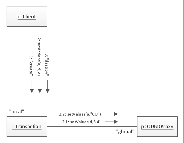
"Communication diagram (called collaboration diagram in UML 1.x) is a kind of UML interaction diagram which shows interactions between objects and/ or parts (represented as lifelines) using sequenced messages in a free-form arrangement.
Communication diagram corresponds (i.e. could be converted to/ from or replaced by) to a simple sequence diagram without structuring mechanisms such as interaction uses and combined fragments. It is also assumed that message overtaking (i.e., the order of the receptions are different from the order of sending of a given set of messages) will not take place or is irrelevant." [uml-diagrams.org/ communication-diagrams.html]
The template "UML communication diagram" for the ConceptDraw PRO diagramming and vector drawing software is included in the Rapid UML solution from the Software Development area of ConceptDraw Solution Park.
www.conceptdraw.com/ solution-park/ software-uml
UML communication diagram
Cisco IBM. Cisco icons, shapes, stencils and symbols

Online Collaboration via Skype


UML Diagram

- Collaboration in a Project Team | Business Collaboration Meaning
- IDEF3 Standard | Collaboration in a Project Team | Draw Two ...
- UML Collaboration Diagram (UML2.0) | Basic Flowchart Symbols ...
- UML Collaboration Diagram (UML2.0) | Basic Flowchart Symbols ...
- Basic Flowchart Symbols and Meaning | Collaboration in a Project ...
- UML Collaboration Diagram (UML2.0) | IDEF0 Diagrams | Basic ...
- Collaboration in a Project Team | Biology | HR Flowcharts | Graphic ...
- Collaboration Diagram Of Online Mobile Recharge
- Collaborative Meaning
- HR symbols - Vector stencils library | HR symbols - Vector stencils ...