Mechanical Drawing Symbols

Process Flowchart


The vector stencils library "Valve assembly" contains 141 symbols of pressure and flow regulators, flow direction indicators, controls, and symbols to design flow paths of control valves.
Use these valve assembly shapes to design the engineering drawings of hydraulic and pneumatic valve assemblies in fluid power systems.
"Control valves are valves used to control conditions such as flow, pressure, temperature, and liquid level by fully or partially opening or closing in response to signals received from controllers that compare a "setpoint" to a "process variable" whose value is provided by sensors that monitor changes in such conditions.
The opening or closing of control valves is usually done automatically by electrical, hydraulic or pneumatic actuators. Positioners are used to control the opening or closing of the actuator based on electric, or pneumatic signals.
A control valve consists of three main parts in which each part exist in several types and designs: Valve's actuator, Valve's positioner, Valve's body.
" [Control valves. Wikipedia]
The shapes example "" was created using the ConceptDraw PRO diagramming and vector drawing software extended with the Mechanical Engineering solution from the Engineering area of ConceptDraw Solution Park.
Valve assembly symbols

Technical Drawing Software

The vector stencils library "Terminals and connectors" contains 43 element symbols of terminals, connectors, plugs, polarized connectors, jacks, coaxial cables, and conductors.
Use it for drawing the wiring diagrams, electrical layouts, electronic schematics, and circuit diagrams.
"An electrical connector is an electro-mechanical device for joining electrical circuits as an interface using a mechanical assembly. Connectors consist of plugs (male-ended) and jacks (female-ended). The connection may be temporary, as for portable equipment, require a tool for assembly and removal, or serve as a permanent electrical joint between two wires or devices. An adapter can be used to effectively bring together dissimilar connectors.
There are hundreds of types of electrical connectors. Connectors may join two lengths of flexible copper wire or cable, or connect a wire or cable or optical interface to an electrical terminal.
In computing, an electrical connector can also be known as a physical interface... Cable glands, known as cable connectors in the US, connect wires to devices mechanically rather than electrically and are distinct from quick-disconnects performing the latter." [Electrical connector. Wikipedia]
"A terminal is the point at which a conductor from an electrical component, device or network comes to an end and provides a point of connection to external circuits. A terminal may simply be the end of a wire or it may be fitted with a connector or fastener. In network analysis, terminal means a point at which connections can be made to a network in theory and does not necessarily refer to any real physical object. In this context, especially in older documents, it is sometimes called a "pole".
The connection may be temporary, as seen in portable equipment, may require a tool for assembly and removal, or may be a permanent electrical joint between two wires or devices.
All electric cell have two terminals. The first is the positive terminal and the second is the negative terminal. The positive terminal looks like a metal cap and the negative terminal looks like a metal disc. The current flows from the positive terminal, and out through the negative terminal, replicative of current flow (positive (+) to negative (-) flow)." [Terminal (electronics). Wikipedia]
The shapes example "Design elements - Terminals and connectors" was drawn using the ConceptDraw PRO diagramming and vector drawing software extended with the Electrical Engineering solution from the Engineering area of ConceptDraw Solution Park.
Terminal and connector symbols

UML Component Diagram. Design Elements
")

Electrical Symbols — Terminals and Connectors

UML Class Diagram. Design Elements

The vector stencils library "Transformers and windings" contains 29 element symbols of transformers, windings, couplers, metering devices, transductors, magnetic cores, chokes, and a variometer.
Use it to design the electromechanical device schematics and electronic circuit diagrams.
"A transformer is an electrical device that transfers energy between two circuits through electromagnetic induction. Transformers may be used in step-up or step-down voltage conversion, which 'transforms' an AC voltage from one voltage level on the input of the device to another level at the output terminals. This special function of transformers can provide control of specified requirements of current level as an alternating current source, or it may be used for impedance matching between mismatched electrical circuits to effect maximum power transfer between the circuits.
A transformer most commonly consists of two windings of wire that are wound around a common core to induce tight electromagnetic coupling between the windings. The core material is often a laminated iron core. The coil that receives the electrical input energy is referred to as the primary winding, while the output coil is called the secondary winding.
An alternating electric current flowing through the primary winding (coil) of a transformer generates an electromagnetic field in its surroundings and a varying magnetic flux in the core of the transformer. By electromagnetic induction this magnetic flux generates a varying electromotive force in the secondary winding, resulting in a voltage across the output terminals. If a load impedance is connected across the secondary winding, a current flows through the secondary winding drawing power from the primary winding and its power source." [Transformer. Wikipedia]
"An electromagnetic coil (or simply a "coil") is formed when a conductor is wound around a core or form to create an inductor or electromagnet. When electricity is passed through a coil, it generates a magnetic field. One loop of wire is usually referred to as a turn or a winding, and a coil consists of one or more turns. For use in an electronic circuit, electrical connection terminals called taps are often connected to a coil. Coils are often coated with varnish or wrapped with insulating tape to provide additional insulation and secure them in place. A completed coil assembly with one or more set of coils and taps is often called the windings.
Windings are used in transformers, electric motors, inductors, solenoids, loudspeakers, and many other applications." [Electromagnetic coil. Wikipedia]
The shapes example "Design elements - Transformers and windings" was drawn using the ConceptDraw PRO diagramming and vector drawing software extended with the Electrical Engineering solution from the Engineering area of ConceptDraw Solution Park.
Transformer and winding symbols

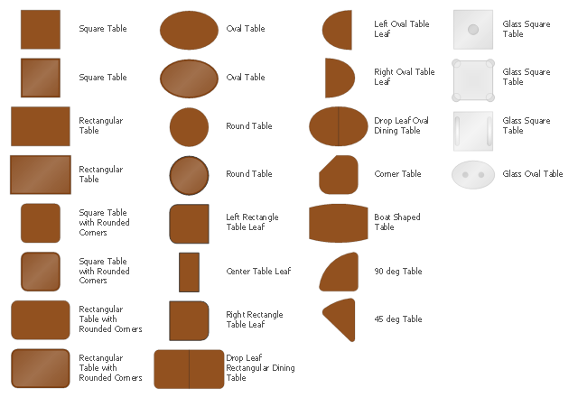
The design elements library Tables contains 27 symbols of tables.
Use the vector stencils library Tables to develop house floor plans, home designs, kitchen and dining room design and furniture layout of cafe or restaurant.
"A table is a form of furniture with a flat horizontal upper surface used to support objects of interest, for storage, show, and/ or manipulation. The surface must be held stable; for reasons of simplicity, this is usually done by support from below by either a column, a "base", or at least three columnar "stands". In special situations, table surfaces may be supported from a nearby wall, or suspended from above.
Common design elements include:
top surfaces of various shapes, including rectangular, rounded, or semi-circular;
legs arranged in two or more similar pairs;
several geometries of folding table that can be collapsed into a smaller volume;
heights ranging up and down from the most common 18–30 inches (46–76 cm) range, often reflecting the height of chairs or bar stools used as seating for people making use of a table, as for eating or performing various manipulations of objects resting on a table;
presence or absence of drawers;
expansion of the surface by insertion of leaves or locking hinged drop leaf sections into horizontal position.
Desks are tables specifically intended for information-manipulation tasks, including writing and use of interactive electronics.
Tables of various shapes, heights, and sizes are designed for specific uses:
Dining room tables are designed to be used for formal dining.
Bedside tables, nightstands, or night tables are small tables used in a bedroom. They are often used for convenient placement of a small lamp, alarm clock, glasses, or other personal items.
Gateleg tables have one or two hinged leaves supported by hinged legs.
Coffee tables are low tables designed for use in a living room, in front of a sofa, for convenient placement of drinks, books, or other personal items.
Refectory tables are long tables designed to seat many people for meals.
Drafting tables usually have a top that can be tilted for making a large or technical drawing. They may also have a ruler or similar element integrated.
Workbenches are sturdy tables, often elevated for use with a high stool or while standing, which are used for assembly, repairs, or other precision handwork.
Nested tables are a set of small tables of graduated size that can be stacked together, each fitting within the one immediately larger. They are for occasional use (such as a tea party), hence the stackable design." [Table (furniture). Wikipedia]
The shapes library Tables is provided by the Floor Plans solution from the Building Plans area of ConceptDraw Solution Park.
UML Deployment Diagram. Design Elements

Flow chart Example. Warehouse Flowchart


Mechanical Design Software

UML Composite Structure Diagram. Design Elements

 Mechanical Engineering
This solution extends ConceptDraw PRO v.9 mechanical drawing software (or later) with samples of mechanical drawing symbols, templates and libraries of design elements, for help when drafting mechanical engineering drawings, or parts, assembly, pneumatic,
- Symbols Used In Industrial Mechanical Assembly Drawings
- Symbols Used In Process Flow Diagram For Mechanical Assembly
- Mechanical Design Symbols Used In Parts Design
- Examples Of Assembly Drawing
- Mechanical Drawing Symbols | Mechanical Engineering ...
- Process Flowchart | Mechanical Drawing Symbols | Technical ...
- Mechanical Assembly Drawing Symbols Pdf
- Mechanical Drawing Symbols | Process Flowchart | Mechanical ...
- Symbol Used In Mechanical Engimeering Drawing
- Mechanical Drawing Symbols | Design elements - Valve assembly ...
- Graphical Symbol Used In Mechanical Engineering Drawing
- Mechanical Assembly Drawing Symbols
- Detail And Assembly Drawing Symbol
- Mechanical Drawing Symbols | Design elements - Valve assembly ...
- Mechanical Drawing Symbols | Mechanical Engineering ...
- Mechanical Parts Assembly Drawing
- Mechanical Drawing Symbols | UML State Machine Diagram.Design ...
- Mechanical Drawing Symbols | Process Flow Diagram Symbols ...
- Mechanical Drawing Symbols | Design elements - Valve assembly ...
- Mechanical Drawing Symbols | Technical Drawing Software ...