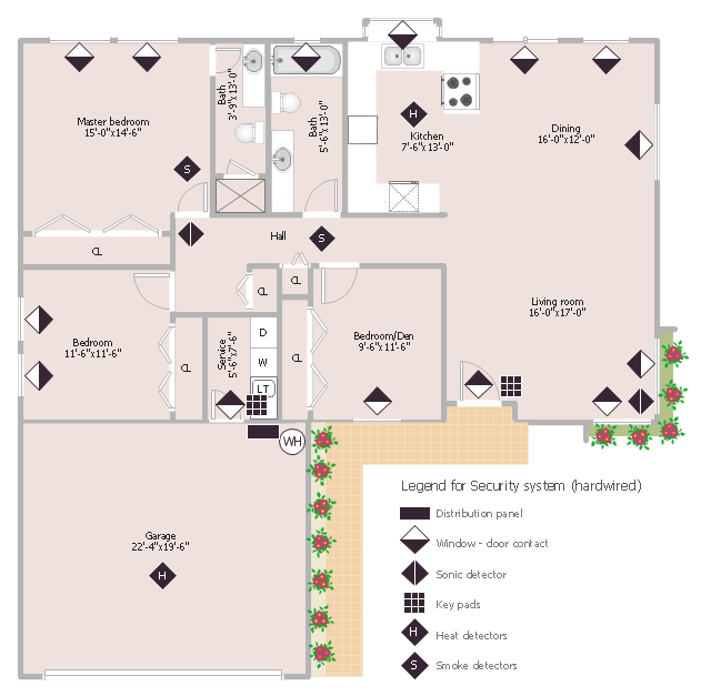
This sample was created on the base of the floor plan with security system device symbols from the website of the California State University, Sacramento. [imet.csus.edu/ imet1/ denyer/ mhs_ denyer/ drafting/ arch_ ch_ 31/ 31-28.jpg]
Legend for the security system hardware includes distribution panel, window-door contact, sonic detector, key pads, heat detectors, smoke detectors.
The example "Security system floor plan" was created using the ConceptDraw PRO diagramming and vector drawing software extended with the Security and Access Plans solution from the Building Plans area of ConceptDraw Solution Park.
Security system floor plan
The vector stencils library Alarm and access control contains 80 symbols of digital proximity equipment, locking hardware, and access control equipment.
"An alarm device or system of alarm devices gives an audible, visual or other form of alarm signal about a problem or condition. Alarm devices are often outfitted with a siren." [Alarm device. Wikipedia]
"An access control point, which can be a door, turnstile, parking gate, elevator, or other physical barrier, where granting access can be electronically controlled. Typically, the access point is a door. An electronic access control door can contain several elements. At its most basic, there is a stand-alone electric lock. The lock is unlocked by an operator with a switch. To automate this, operator intervention is replaced by a reader. The reader could be a keypad where a code is entered, it could be a card reader, or it could be a biometric reader. Readers do not usually make an access decision, but send a card number to an access control panel that verifies the number against an access list. To monitor the door position a magnetic door switch can be used. In concept, the door switch is not unlike those on refrigerators or car doors. Generally only entry is controlled, and exit is uncontrolled. In cases where exit is also controlled, a second reader is used on the opposite side of the door. In cases where exit is not controlled, free exit, a device called a request-to-exit (REX) is used. Request-to-exit devices can be a push-button or a motion detector. When the button is pushed, or the motion detector detects motion at the door, the door alarm is temporarily ignored while the door is opened. Exiting a door without having to electrically unlock the door is called mechanical free egress. This is an important safety feature. In cases where the lock must be electrically unlocked on exit, the request-to-exit device also unlocks the door." [Access control. Wikipedia]
Use the design elements library Alarm and access control for drawing layout floor plans, blueprints, and wiring diagrams of intrusion systems, time and attendance systems, card and code access control security systems, internal and external security control systems using the ConceptDraw PRO diagramming and vector drawing software.
The shapes library Alarm and access control is included in the Security and Access Plans solution from the Building Plans area of ConceptDraw Solution Park.
Alarm and access control symbols

How To use House Electrical Plan Software


Physical Security Plan

The vector stencils library Initiation and annunciation contains 9 symbols of Fire Alarm Control Panel (FACP) or Fire Alarm Control Unit (FACU) elements, triggering devices, audible alarm systems, timers, security control equipment, and recording devices.
"A Fire Alarm Control Panel (FACP), or Fire Alarm Control Unit (FACU), is the controlling component of a Fire Alarm System. The panel receives information from environmental sensors designed to detect changes associated with fire, monitors their operational integrity and provides for automatic control of equipment, and transmission of information necessary to prepare the facility for fire based on a predetermined sequence. The panel may also supply electrical energy to operate any associated sensor, control, transmitter, or relay. There are four basic types of panels: coded panels, conventional panels, addressable panels, and multiplex systems." [Fire alarm control panel. Wikipedia]
Use the shapes library Initiation and annunciation to draw layout floor plans, communications schematics and wiring diagrams of security systems using the ConceptDraw PRO diagramming and vector drawing software.
The design elements library Initiation and annunciation is included in the Security and Access Plans solution from the Building Plans area of ConceptDraw Solution Park.
Initiation and annunciation symbols

 Security and Access Plans
This solution extends ConceptDraw PRO software with physical security plan, security chart, access chart, security plans, access schemes, access plans , CCTV System Plan samples, templates and libraries of design elements for drawing the Security and Acce
Security Plans

Cisco Routers. Cisco icons, shapes, stencils and symbols
 Router subdued Router-with-silicon-switch Wavelength-router NetFlow-router uBR910 Broadband-router Gigabit-switch-ATM-tag-router ATM-tag-switch-router Edge-label-switch-router Edge-label-switch-router-with-NetFlow Cisco-7505 Cisco-7507 Cisco-7500-ARS-(7513) Voice-enabled-router TDM-router IP-telephony-router IAD-router Content-service-router Cisco-storage-router Router-with-firewall Wireless-router ASR-1000-series ATM-3800 AXP Cable-modem Ground-terminal. Network equipment refers to hardware devices designed for local area networks, both wired and wireless. Active network equipment is powered from the electricity supply, portable battery, the computer via USB-port and other sources, also it can be used for amplification, conversion and processing of the network signal.")
Electrical Symbols — Electrical Circuits

"HVAC (stands for Heating, Ventilation and Air Conditioning) is a control system that applies regulation to a heating and/ or air conditioning system. Usually a sensing device is used to compare the actual state (e.g., temperature) with a target state. Then the control system draws a conclusion what action has to be taken (e.g., start the blower).
More complex HVAC systems can interface to Building Automation System (BAS) to allow the building owners to have more control over the heating or cooling units. The building owner can monitor the system and respond to alarms generated by the system from local or remote locations." [HVAC control system. Wikipedia]
The vector stencils library "HVAC control equipment" contains 48 symbols of heating, ventilation, air conditioning, refrigeration and automated building control equipment.
Use the design elements library HVAC control equipment to draw HVAC plans, schematic diagrams of heating, ventilation, air conditioning, refrigeration and automated building control systems, environmental control design building plans and equipment layouts using the ConceptDraw PRO diagramming and vector drawing software.
The shapes library HVAC control equipment is contained in the HVAC Plans solution from the Building Plans area of ConceptDraw Solution Park.
HVAC control equipment symbols

HelpDesk
How to Create a Network Security Diagram Using ConceptDraw PRO

The vector stencils library "HVAC controls" contains 23 symbols of HVAC controls (sensors, actuators, timers, controllers, I/ O points).
"HVAC (... Heating, Ventilation and Air Conditioning) is a control system that applies regulation to a heating and/ or air conditioning system. ...
Central controllers and most terminal unit controllers are programmable, meaning the direct digital control program code may be customized for the intended use. The program features include time schedules, setpoints, controllers, logic, timers, trend logs, and alarms. The unit controllers typically have analog and digital inputs that allow measurement of the variable (temperature, humidity, or pressure) and analog and digital outputs for control of the transport medium (hot/ cold water and/ or steam). Digital inputs are typically (dry) contacts from a control device, and analog inputs are typically a voltage or current measurement from a variable (temperature, humidity, velocity, or pressure) sensing device. Digital outputs are typically relay contacts used to start and stop equipment, and analog outputs are typically voltage or current signals to control the movement of the medium (air/ water/ steam) control devices such as valves, dampers, and motors." [HVAC control system. Wikipedia]
Use the design elements library "HVAC controls" for drawing the HVAC system diagrams, controls drawings, and automated building control and environmental control system layuout floor plans using the ConceptDraw PRO diagramming and vector drawing software.
The shapes library "HVAC controls" is included in the HVAC Plans solution from the Building Plans area of ConceptDraw Solution Park.
HVAC control symbols

Fire Evacuation Plan Template

Create Floor Plans Easily with ConceptDraw PRO


Business Process Workflow Diagram


- Security system plan
- Security system floor plan | How To use House Electrical Plan ...
- Security System Door Contact Symbols
- Security and Access Plans | How to Draw a Security and Access ...
- Security system plan | Floor Plan For Self Contain And Symbol
- Design elements - Doors and windows | Security system floor plan ...
- HVAC controls - Vector stencils library | Security system floor plan ...
- Alarm Cct Symbol
- Security system floor plan | Design elements - Doors and windows ...
- How To use House Electrical Plan Software | Security system floor ...
- | Car Alarm Symbols
- Break Glass Plan Symbol
- Casement Door Symbols
- Fire Alarm Symbol
- Security system plan | Design elements - Alarm and access control ...
- Fire Alarm System Drawing Symbols
- Refrigerator Symbol Floor Plan
- Smoke alarm equipment layout floor plan | Fire Alarm Indicator Symbol
- Draw Wiring Diagram Security System
- Schematic Symbol Fire Alarm