"State machine diagram is a behavior diagram which shows discrete behavior of a part of designed system through finite state transitions. State machine diagrams can also be used to express the usage protocol of part of a system. Two kinds of state machines defined in UML 2.4 are:
(1) behavioral state machine, and
(2) protocol state machine.
The following nodes and edges are typically drawn in state machine diagram: behavioral state, behavioral transition, protocol state, protocol transition, different pseudostates. ...
Behavioral state machine is specialization of behavior and is used to specify discrete behavior of a part of designed system through finite state transitions. The state machine formalism used in this case is an object-based variant of Harel statecharts.
Behavior is modeled as a traversal of a graph of state nodes connected with transitions. Transitions are triggered by the dispatching of series of events. During the traversal, the state machine could also execute some activities. ...
Protocol state machine is a specialization of behavioral state machine and is used to express usage protocol or lifecycle of a classifier. It specifies which operations of the classifier can be called in which state and under which condition, thus specifying the allowed call sequences on the classifier’s operations. Protocol state machines express the legal transitions that a classifier can trigger." [uml-diagrams.org/ state-machine-diagrams.html]
The template "UML state machine diagram" for the ConceptDraw PRO diagramming and vector drawing software is included in the Rapid UML solution from the Software Development area of ConceptDraw Solution Park.
www.conceptdraw.com/ solution-park/ software-uml
UML state machine diagram

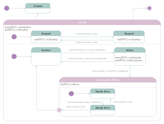
"RT-middleware (Robotics Technology Middleware) is a common platform standards for Robots based on the distributed object technology. RT-middleware supports the construction of various networked robotic systems by the integration of various network enabled robotic elements called RT-Components. The specification standard of the RT-component is discussed / defined by the Object Management Group (OMG). ...
In the RT-middleware, robotics elements, such as actuators, are regarded as RT-components, and the whole robotic system is constructed by connecting those RT-components. This distributed architecture helps developers to re-use the robotic elements, and boosts the reliability of the robotic system.
Each RT-component has port as an endpoint for communicating other RT-components. Every port has its type and the ports which have the same type can be connected each other.
RT-components also has its state, so the RT-components behaves as state machines. The states that RT-components can have are CREATED, INACTIVE, ACTIVE, and ERROR, and the states and behaviors are controlled by the execution-context. If developers want to change the behavior of their RT-components, the execution-context can be replaced at run-time." [RT middleware. Wikipedia]
The UML state machine diagram example "State transitions of RT-component" was created using the ConceptDraw PRO diagramming and vector drawing software extended with the Rapid UML solution from the Software Development area of ConceptDraw Solution Park.
UML state machine diagram
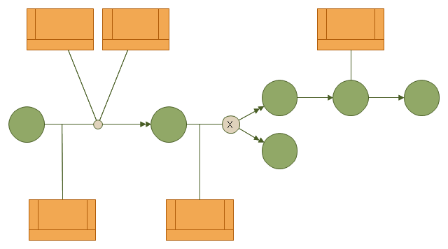
This IDEF3 diagram example was redesigned from the Wikimedia Commons file: 6-4 Example IDEF3 Object State Transition Schematic.jpg.
[commons.wikimedia.org/ wiki/ File:6-4_ Example_ IDEF3_ Object_ State_ Transition_ Schematic.jpg]
"Quick Reading of IDEF3 Process Descriptions: An Example.
An example approach for reading a schematic is described in the following steps. This outline for reading a schematic would be repeated, with few modifications, for all decompositions, whether found in a Process Schematic or an Object Schematic. In general, decompositions are read after the parent schematic has been read and understood.
The Big Picture.
A crucial step in the description-reading process is to understand the big picture
relevant to the real-life situation described. This big picture can be gained by reading and understanding the statement of purpose, statement of scope, objective of the scenario being described, and viewpoint of the IDEF3 Process Description. ...
Scan the Schematic.
Readers should become familiar with the scenario by scanning the schematic from left to right. This involves becoming familiar with the individual elements (e.g., UOBs, links, and junctions) displayed in the schematic. This is not an in-depth study of the schematic; rather, it provides readers with a general impression of the process being described and an overall understanding of the logic flow in the scenario.
Understand the Description.
In this step, readers gain a detailed understanding of the schematic associated with a scenario, object, or a decomposition of a schematic element. This is the part of the communication process that is most individualized and requires the most time. It is helpful to partition the schematic into understandable pieces." [IDEF3 Process Description Capture Method Report AL-TR-1995-XXXX. idef.com/ pdf/ Idef3_ fn.pdf]
The diagram sample "IDEF3 object state transition schematic" was created using the ConceptDraw PRO diagramming and vector drawing software extended with the solution "IDEF Business Process Diagrams" from the area "Business Processes" of ConceptDraw Solution Park.
IDEF3 business process diagram
IDEF3 Standard

The vector stencils library "Bank UML state machine diagram" contains 21 shapes for drawing UML state machine diagrams.
Use it for object-oriented modeling of your bank information system.
"The state diagram in the Unified Modeling Language is essentially a Harel statechart with standardized notation, which can describe many systems, from computer programs to business processes. In UML 2 the name has been changed to State Machine Diagram. The following are the basic notational elements that can be used to make up a diagram:
* Filled circle, pointing to the initial state.
* Hollow circle containing a smaller filled circle, indicating the final state (if any).
* Rounded rectangle, denoting a state. Top of the rectangle contains a name of the state. Can contain a horizontal line in the middle, below which the activities that are done in that state are indicated.
* Arrow, denoting transition. The name of the event (if any) causing this transition labels the arrow body. A guard expression may be added before a "/ " and enclosed in square-brackets ( eventName[guardExpression] ), denoting that this expression must be true for the transition to take place. If an action is performed during this transition, it is added to the label following a "/ " ( eventName[guardExpression]/ action ).
* Thick horizontal line with either x>1 lines entering and 1 line leaving or 1 line entering and x>1 lines leaving. These denote join/ fork, respectively." [State machine diagram. Wikipedia]
This example of UML state machine diagram symbols for the ConceptDraw PRO diagramming and vector drawing software is included in the ATM UML Diagrams solution from the Software Development area of ConceptDraw Solution Park.
UML state machine diagram symbols

 IDEF Business Process Diagrams
Use the IDEF Business Process Diagrams solution to create effective database designs and object-oriented designs, following the integration definition methodology.
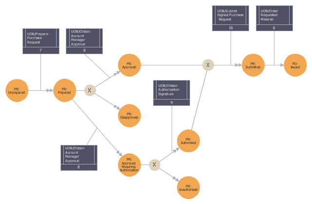
This IDEF3 diagram example was redesigned from the Wikimedia Commons file: 5-21 Completed Transition Schematic.jpg.
[commons.wikimedia.org/ wiki/ File:5-21_ Completed_ Transition_ Schematic.jpg]
"As with the Process Schematic, the correctness of the Object Schematic and
associated elaborations are confirmed through validation with the domain expert. After reviewing the Transition Schematic, the domain expert observes that the allowable state transitions displayed in the schematic do not include those representative of a failed request. ...
The domain expert also identified transitions through which the identity of the object was preserved and transitions where the object was actually transformed into an entirely different object. The domain expert’s comments to the analyst yield the schematic
depicted in Figure 5-21." [IDEF3 Process Description Capture Method Report AL-TR-1995-XXXX. idef.com/ pdf/ Idef3_ fn.pdf]
The sample "Completed transition schematic - IDEF3 diagram" was created using the ConceptDraw PRO diagramming and vector drawing software extended with the solution "IDEF Business Process Diagrams" from the area "Business Processes" of ConceptDraw Solution Park.
IDEF3 business process diagram
The vector stencils library "UML state machine diagrams" contains 35 symbols for the ConceptDraw PRO diagramming and vector drawing software.
"The state diagram in the Unified Modeling Language is essentially a Harel statechart with standardized notation, which can describe many systems, from computer programs to business processes. In UML 2 the name has been changed to State Machine Diagram. The following are the basic notational elements that can be used to make up a diagram:
(1) Filled circle, pointing to the initial state.
(2) Hollow circle containing a smaller filled circle, indicating the final state (if any).
(3) Rounded rectangle, denoting a state. Top of the rectangle contains a name of the state. Can contain a horizontal line in the middle, below which the activities that are done in that state are indicated.
(4) Arrow, denoting transition. The name of the event (if any) causing this transition labels the arrow body. A guard expression may be added before a "/ " and enclosed in square-brackets ( eventName[guardExpression] ), denoting that this expression must be true for the transition to take place. If an action is performed during this transition, it is added to the label following a "/ " ( eventName[guardExpression]/ action ).
(5) Thick horizontal line with either x>1 lines entering and 1 line leaving or 1 line entering and x>1 lines leaving. These denote join/ fork, respectively." [State diagram (UML). Wikipedia]
The example "Design elements - UML state machine diagrams" is included in the Rapid UML solution from the Software Development area of ConceptDraw Solution Park.
UML state machine diagram symbols

- State Transition Diagram Of Book Shop To Sales Books
- Rapid UML | Rapid UML | State Transition Diagram In Computer ...
- State Transition Diagram For Online Bookstore
- State Transition Diagram For Shop
- UML Diagram | State Transition Diagram For Bank Database In ...
- State Transition Diagram Of Atm System
- UML state machine diagram - State transitions of RT-component ...
- Rapid UML | IDEF3 Standard | State Transition Diagram In Uml ...
- UML state machine diagram - State transitions of RT-component ...
- Rapid UML | Rapid UML | State Transition Diagram For Education ...
- State Diagram Example - Online Store | UML Component Diagram ...
- State Transition Diagram For Atm System
- UML state machine diagram
- State Transition Diagram Of Gui Of Software
- Vector stencils library - State machine diagram | UML state machine ...
- UML state machine diagram - State transitions of RT-component
- Completed transition schematic - IDEF3 diagram | Transition ...
- UML state machine diagram - State transitions of RT-component | Rt ...
- UML state machine diagram - Template