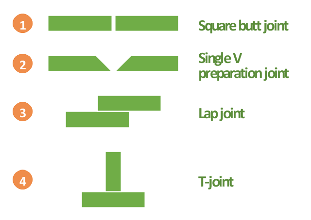
"A welding joint is a point or edge where two or more pieces of metal or plastic are joined together. They are formed by welding two or more workpieces (metal or plastic) according to a particular geometry. Five types of joints referred to by the American Welding Society: butt, corner, edge, lap, and tee. These configurations may have various configurations at the joint where actual welding can occur." [Welding joint. Wikipedia]
This engineering drawing example was redesigned using the ConceptDraw PRO diagramming and vector drawing software from the Wikimedia Commons file: Common joint types.png.
[commons.wikimedia.org/ wiki/ File:Common_ joint_ types.png]
This file is licensed under the Creative Commons Attribution-Share Alike 3.0 Unported license.
[creativecommons.org/ licenses/ by-sa/ 3.0/ deed.en]
The engineering drawing example "Common joint types" is included in the Mechanical Engineering solution from the Engineering area of ConceptDraw Solution Park.
Welding joint types
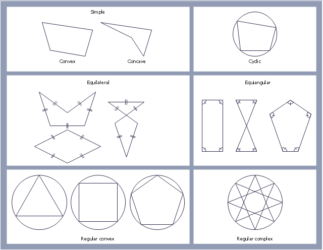
"In geometry a polygon is traditionally a plane figure that is bounded by a finite chain of straight line segments closing in a loop to form a closed chain or circuit. These segments are called its edges or sides, and the points where two edges meet are the polygon's vertices (singular: vertex) or corners. The interior of the polygon is sometimes called its body. An n-gon is a polygon with n sides. A polygon is a 2-dimensional example of the more general polytope in any number of dimensions. ...
The basic geometrical notion has been adapted in various ways to suit particular purposes. Mathematicians are often concerned only with the bounding closed polygonal chain and with simple polygons which do not self-intersect, and they often define a polygon accordingly. A polygonal boundary may be allowed to intersect itself, creating star polygons. Geometrically two edges meeting at a corner are required to form an angle that is not straight (180°); otherwise, the line segments may be considered parts of a single edge; however mathematically, such corners may sometimes be allowed. These and other generalizations of polygons are described below." [Polygon. Wikipedia]
The geometry diagram example "Polygon types" was created using the ConceptDraw PRO diagramming and vector drawing software extended with the Mathematics solution from the Science and Education area of ConceptDraw Solution Park.
Polygon types
Basic Flowchart Symbols and Meaning


Bubble diagrams in Landscape Design with ConceptDraw PRO

HelpDesk
How to Create a Timeline Diagram in ConceptDraw PRO

IDEF4 Standard

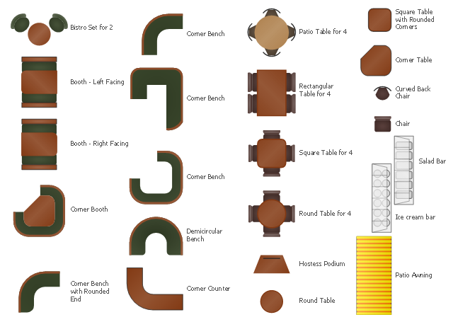
The vector stencils library Cafe and restaurant contains symbols of furniture, equipment and interior design elenebts.
Use the shapes library Cafe and restaurant to draw the interior design floor plans and furniture and equipment layouts of coffeehouses, restaurants and bars using the ConceptDraw PRO diagramming and vector drawing software.
"Various types of restaurant fall into several industry classifications based upon menu style, preparation methods and pricing. Additionally, how the food is served to the customer helps to determine the classification.
Historically, restaurant referred only to places that provided tables where one sat down to eat the meal, typically served by a waiter. Following the rise of fast food and take-out restaurants, a retronym for the older "standard" restaurant was created, sit-down restaurant. Most commonly, "sit-down restaurant" refers to a casual dining restaurant with table service, rather than a fast food restaurant or a "diner", where one orders food at a counter." [Types of restaurant. Wikipedia]
The design elements library Cafe and restaurant is included in the Cafe and Restaurant Floor Plans solution from the Building Plans area of ConceptDraw Solution Park.
Geo Map - Canada - New Brunswick

HelpDesk
How to Set Line Jumps for Smart Connectors in ConceptDraw PRO

This engineering drawing shows different types of geometry of butt welds.
"Welds can be geometrically prepared in many different ways. The five basic types of weld joints are the butt joint, lap joint, corner joint, edge joint, and T-joint (a variant of this last is the cruciform joint). Other variations exist as well - for example, double-V preparation joints are characterized by the two pieces of material each tapering to a single center point at one-half their height. Single-U and double-U preparation joints are also fairly common - instead of having straight edges like the single-V and double-V preparation joints, they are curved, forming the shape of a U. Lap joints are also commonly more than two pieces thick - depending on the process used and the thickness of the material, many pieces can be welded together in a lap joint geometry." [Welding. Wikipedia]
This engineering drawing example was redesigned using the ConceptDraw PRO diagramming and vector drawing software from the Wikimedia Commons file: Butt Weld Geometry.GIF.
[commons.wikimedia.org/ wiki/ File:Butt_ Weld_ Geometry.GIF]
The engineering drawing example "Butt weld geometry" is included in the Mechanical Engineering solution from the Engineering area of ConceptDraw Solution Park.
Welding joint diagram

Garrett IA Diagrams with ConceptDraw PRO

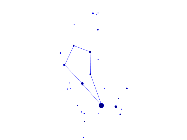
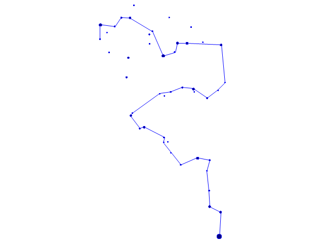
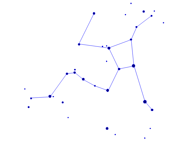
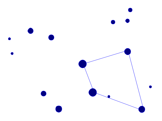
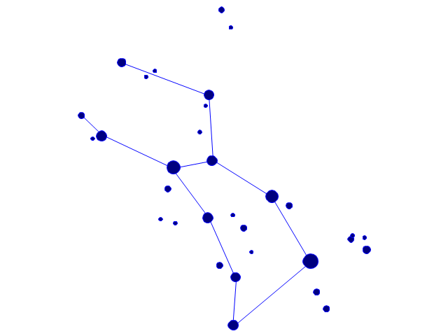
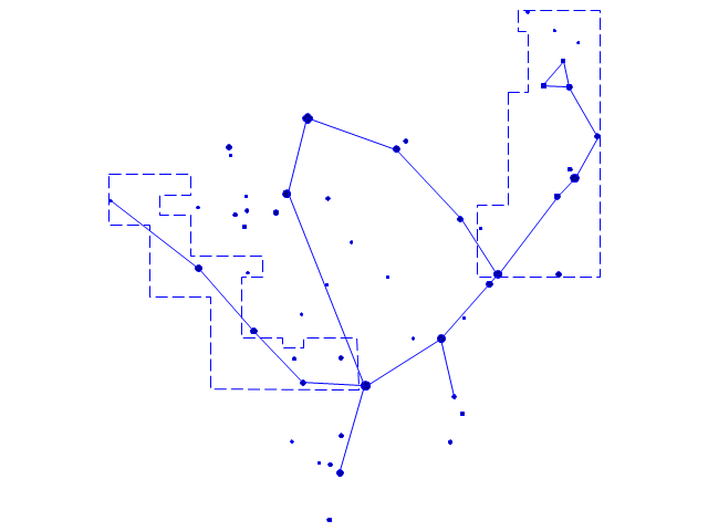
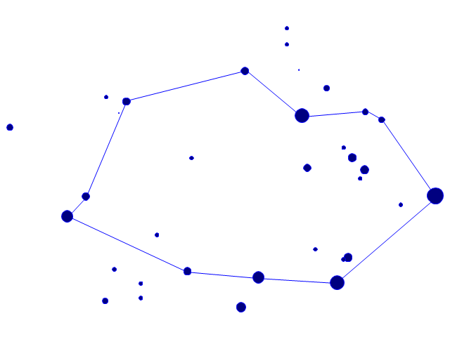
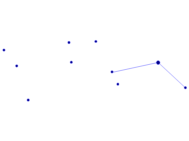
The vector stencils library "Constellations except Zodiac, Northern and Southern" contains 47 star constellation maps of all constellations except Zodiac, Northern (45-90 degrees) and Southern (45-90 degrees).
Use these shapes for drawing astronomical diagrams and illustrations in ConceptDraw PRO diagramming and vector drawing software extended with the Astronomy solution from the Science and Education area in ConceptDraw Solution Park.
Use these shapes for drawing astronomical diagrams and illustrations in ConceptDraw PRO diagramming and vector drawing software extended with the Astronomy solution from the Science and Education area in ConceptDraw Solution Park.
Andromeda

Antlia

Aquila

Auriga

Bootes
Caelum

Canes Venatici

Canis Major

Canis Minor

Centaurus

Cetus

Columba
Coma Berenices

Corona Australis
Corona Borealis

Corvus
Crater

Cygnus

Delphinus

Equuleus
Eridanus
Fornax

Grus

Hercules
Hydra

Lacerta

Leo Minor

Lepus
Lupus
Lynx

Lyra

Microscopium
Monoceros

Ophiuchus and Serpens
Orion

Pegasus

Perseus

Piscis Austrinus
Puppis

Pyxis

Sagitta
Sculptor
Scutum
Sextans
Triangulum
Vela
Vulpecula
The vector stencils library "Constellations except Zodiac, Northern and Southern" contains 47 star constellation maps of all constellations except Zodiac, Northern (45-90 degrees) and Southern (45-90 degrees).
Use these shapes for drawing astronomical diagrams and illustrations in ConceptDraw PRO diagramming and vector drawing software extended with the Astronomy solution from the Science and Education area in ConceptDraw Solution Park.
Use these shapes for drawing astronomical diagrams and illustrations in ConceptDraw PRO diagramming and vector drawing software extended with the Astronomy solution from the Science and Education area in ConceptDraw Solution Park.
Andromeda
Antlia
Aquila
Auriga
Bootes
Caelum
Canes Venatici
Canis Major
Canis Minor
Centaurus
Cetus
Columba
Coma Berenices
Corona Australis
Corona Borealis
Corvus
Crater
Cygnus
Delphinus
Equuleus
Eridanus
Fornax
Grus
Hercules
Hydra
Lacerta
Leo Minor
Lepus
Lupus
Lynx
Lyra
Microscopium
Monoceros
Ophiuchus and Serpens
Orion
Pegasus
Perseus
Piscis Austrinus
Puppis
Pyxis
Sagitta
Sculptor
Scutum
Sextans
Triangulum
Vela
Vulpecula
Geo Map — Europe — Poland

The vector stencils library "Welding" contains 38 welding joint symbols to identify fillets, contours, resistance seams, grooves, surfacing, and backing.
Use it to indicate welding operations on working drawings.
"Welding is a fabrication or sculptural process that joins materials, usually metals or thermoplastics, by causing coalescence. This is often done by melting the workpieces and adding a filler material to form a pool of molten material (the weld pool) that cools to become a strong joint, with pressure sometimes used in conjunction with heat, or by itself, to produce the weld. This is in contrast with soldering and brazing, which involve melting a lower-melting-point material between the workpieces to form a bond between them, without melting the workpieces.
Many different energy sources can be used for welding, including a gas flame, an electric arc, a laser, an electron beam, friction, and ultrasound.
Welds can be geometrically prepared in many different ways. The five basic types of weld joints are the butt joint, lap joint, corner joint, edge joint, and T-joint (a variant of this last is the cruciform joint). Other variations exist as well - for example, double-V preparation joints are characterized by the two pieces of material each tapering to a single center point at one-half their height. Single-U and double-U preparation joints are also fairly common - instead of having straight edges like the single-V and double-V preparation joints, they are curved, forming the shape of a U. Lap joints are also commonly more than two pieces thick - depending on the process used and the thickness of the material, many pieces can be welded together in a lap joint geometry." [Welding. Wikipedia]
The shapes example "Design elements - Welding" was created using the ConceptDraw PRO diagramming and vector drawing software extended with the Mechanical Engineering solution from the Engineering area of ConceptDraw Solution Park.
Welding joint symbols

- Square Types
- Basic Flowchart Symbols and Meaning | Types Of Dfd Circle Square ...
- Welded joints types
- Types Of Square
- Symbol Fol Square Butt Weld
- Lap Joint Types Engineering Drawing
- Butt weld geometry | Square Butt Weld Diagram
- Butt weld geometry | Design elements - Welding | Common joint ...
- Sketches Of Square Butt
- Butt weld geometry | Welded joints types | Welding - Vector stencils ...
- Welded joints types | Welding symbols | Butt weld geometry ...
- Butt weld geometry | Welded joints types | Design elements ...
- Butt weld geometry | Common joint types | Welded joints types ...
- Common joint types | Welded joints types | Butt weld geometry ...
- Butt weld geometry | Polygon types | Mathematics | Types Of ...
- Butt weld geometry | Welded joints types | Elements location of a ...
- Welded joints types | Mechanical Engineering | Butt weld geometry ...
- Polygon types | Mathematics Symbols | IDEF4 Standard | Types Of ...
- Butt weld geometry | Welded joints types | Mechanical Engineering ...
- Common joint types