Basic Flowchart Symbols and Meaning


Entity Relationship Diagram Symbols

ERD Symbols and Meanings


Mathematics Symbols

Electrical Symbols — Switches and Relays

 Mathematics
Mathematics solution extends ConceptDraw DIAGRAM software with templates, samples and libraries of vector stencils for drawing the mathematical illustrations, diagrams and charts.
Technical Drawing Software

Bubble diagrams in Landscape Design with ConceptDraw DIAGRAM

The vector stencils library "Dimensioning" contains 18 dimensions shapes.
Use it to create your landscape design and garden plans.
"Geometric dimensioning and tolerancing (GD&T) is a system for defining and communicating engineering tolerances. It uses a symbolic language on engineering drawings and computer-generated three-dimensional solid models that explicitly describes nominal geometry and its allowable variation. It tells the manufacturing staff and machines what degree of accuracy and precision is needed on each controlled feature of the part. GD&T is used to define the nominal (theoretically perfect) geometry of parts and assemblies, to define the allowable variation in form and possible size of individual features, and to define the allowable variation between features.
Dimensioning specifications define the nominal, as-modeled or as-intended geometry. One example is a basic dimension." [Geometric dimensioning and tolerancing. Wikipedia]
The dimensions shapes example "Design elements - Dimensioning" was created using the ConceptDraw PRO diagramming and vector drawing software extended with the Landscape & Garden solution from the Building Plans area of ConceptDraw Solution Park.
Dimension shapes

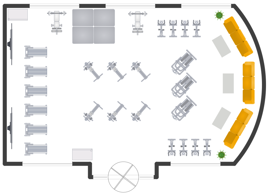
Gym Layout
- Entity Relationship Diagram Symbols | ERD Symbols and Meanings ...
- How to Draw Geometric Shapes in ConceptDraw PRO ...
- Design elements - Solid geometry | How to Draw Geometric Shapes ...
- Solid geometry - Vector stencils library | Flowchart design. Flowchart ...
- How to Draw Geometric Shapes in ConceptDraw PRO | Design ...
- How to Draw Geometric Shapes in ConceptDraw PRO | Design ...
- Design elements - Solid geometry | Solid geometry - Vector stencils ...
- Mathematical Diagrams | How to Draw Geometric Shapes in ...
- Mathematics Symbols | Mathematical Diagrams | How to Draw ...
- Office Layout Plans | How to Draw Geometric Shapes in ...