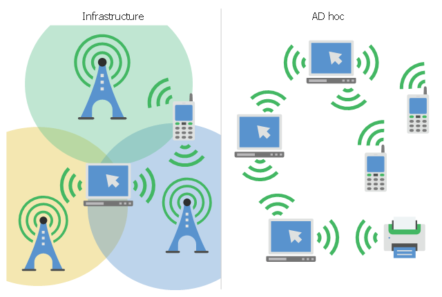
This infographic sample visualizes the Conventional and wireless ad hoc network. It was designed on the base of the Wikimedia Commons file: Běžná bezdrátová síť a ad hoc síť.png.
[commons.wikimedia.org/ wiki/ File:B%C4%9B%C5%BEn%C3%A1_ bezdr%C3%A1tov%C3%A1_ s%C3%AD%C5%A5_ a_ ad_ hoc_ s%C3%AD%C5%A5.png]
This file is licensed under the Creative Commons Attribution-Share Alike 4.0 International license. [creativecommons.org/ licenses/ by-sa/ 4.0/ deed.en]
"A wireless ad hoc network (WANET) is a decentralized type of wireless network. The network is ad hoc because it does not rely on a pre existing infrastructure, such as routers in wired networks or access points in managed (infrastructure) wireless networks. Instead, each node participates in routing by forwarding data for other nodes, so the determination of which nodes forward data is made dynamically on the basis of network connectivity. In addition to the classic routing, ad hoc networks can use flooding for forwarding data.
Wireless mobile ad hoc networks are self-configuring, dynamic networks in which nodes are free to move. Wireless networks lack the complexities of infrastructure setup and administration, enabling devices to create and join networks "on the fly" – anywhere, anytime." [Wireless ad hoc network. Wikipedia]
The infographic example "Conventional and wireless ad hoc network" was created using the ConceptDraw PRO diagramming and vector drawing software extended with the Computers and Communications solution from the Illustration area of ConceptDraw Solution Park.
Network infographic
This purchase order processing UML activity diagram was created on the base of activity diagram from the software architecture documentation wiki of the Software Engineering Institute (SEI) of Carnegie Mellon University (CMU).
[wiki.sei.cmu.edu/ sad/ index.php/ Image:PurchaseOrderActivityDiagram.png]
"A purchase order (PO) is a commercial document and first official offer issued by a buyer to a seller, indicating types, quantities, and agreed prices for products or services. Acceptance of a purchase order by a seller forms a contract between the buyer and seller, so no contract exists until the purchase order is accepted. It is used to control the purchasing of products and services from external suppliers.
Creating a purchase order is typically the first step of the purchase to pay process in an ERP system." [Purchase order. Wikipedia]
This purchase order processing UML activity diagram example was created using the ConceptDraw PRO diagramming and vector drawing software extended with the ATM UML Diagrams solution from the Software Development area of ConceptDraw Solution Park.
UML activity diagram of purchase order processing

Star Network Topology


The circuit diagram example "Bipolar current mirror" was redesigned from the Wikipedia file: Current mirror.png.
[en.wikipedia.org/ wiki/ File:Current_ mirror.png]
This file is licensed under the Creative Commons Attribution-Share Alike 3.0 Unported license. [creativecommons.org/ licenses/ by-sa/ 3.0/ deed.en]
"A current mirror is a circuit designed to copy a current through one active device by controlling the current in another active device of a circuit, keeping the output current constant regardless of loading. The current being 'copied' can be, and sometimes is, a varying signal current. Conceptually, an ideal current mirror is simply an ideal inverting current amplifier that reverses the current direction as well or it is a current-controlled current source (CCCS). The current mirror is used to provide bias currents and active loads to circuits. ...
Basic BJT current mirror.
If a voltage is applied to the BJT base-emitter junction as an input quantity and the collector current is taken as an output quantity, the transistor will act as an exponential voltage-to-current converter. By applying a negative feedback (simply joining the base and collector) the transistor can be "reversed" and it will begin acting as the opposite logarithmic current-to-voltage converter; now it will adjust the "output" base-emitter voltage so as to pass the applied "input" collector current.
The simplest bipolar current mirror ... implements this idea. It consists of two cascaded transistor stages acting accordingly as a reversed and direct voltage-to-current converters." [Current mirror. Wikipedia]
The circuit diagram example "Bipolar current mirror" was created using the ConceptDraw PRO diagramming and vector drawing software extended with the Electrical Engineering solution from the Engineering area of ConceptDraw Solution Park.
Circuit diagram

Electrical Symbols — Analog and Digital Logic

How to Draw a Computer Network Diagrams

The vector stencils library "Analog and digital logic" contains 40 element symbols of logic (threshold) gates, bistable current switches, current controllers, regulators, electrical generators, and amplifiers.
Use it for drawing the digital and analog functions in electronic circuit diagrams and electrical schematics.
"Analogue electronics (or analog in American English) are electronic systems with a continuously variable signal, in contrast to digital electronics where signals usually take only two different levels. The term "analogue" describes the proportional relationship between a signal and a voltage or current that represents the signal." [Analogue electronics. Wikipedia]
"Digital electronics, or digital (electronic) circuits, represent signals by discrete bands of analog levels, rather than by a continuous range. All levels within a band represent the same signal state. Relatively small changes to the analog signal levels due to manufacturing tolerance, signal attenuation or parasitic noise do not leave the discrete envelope, and as a result are ignored by signal state sensing circuitry.
In most cases the number of these states is two, and they are represented by two voltage bands: one near a reference value (typically termed as "ground" or zero volts) and a value near the supply voltage, corresponding to the "false" ("0") and "true" ("1") values of the Boolean domain respectively.
Digital techniques are useful because it is easier to get an electronic device to switch into one of a number of known states than to accurately reproduce a continuous range of values.
Digital electronic circuits are usually made from large assemblies of logic gates, simple electronic representations of Boolean logic functions." [Digital electronics. Wikipedia]
The example "Design elements - Analog and digital logic" was drawn using the ConceptDraw PRO diagramming and vector drawing software extended with the Electrical Engineering solution from the Engineering area of ConceptDraw Solution Park.
Analog and digital logic elements

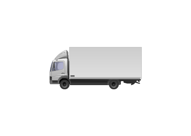
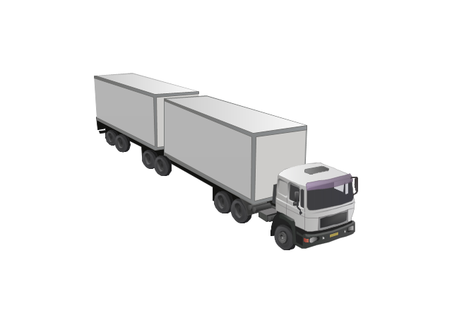
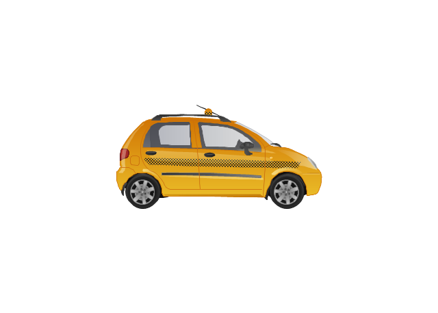
The vector stencils library "Road transport" contains 43 clip art images for creating vehicles and transportation illustrations, presentation slides, infographics and webpages using the ConceptDraw PRO diagramming and vector drawing software.
"Road transport (British English) or road transportation (American English) is the transport of passengers or goods on roads. ...
Transportation.
Transport on roads can be roughly grouped into the transportation of goods and transportation of people. In many countries licencing requirements and safety regulations ensure a separation of the two industries.
The nature of road transportation of goods depends, apart from the degree of development of the local infrastructure, on the distance the goods are transported by road, the weight and volume of the individual shipment, and the type of goods transported. For short distances and light, small shipments a van or pickup truck may be used. For large shipments even if less than a full truckload a truck is more appropriate. In some countries cargo is transported by road in horse-drawn carriages, donkey carts or other non-motorized mode. Delivery services are sometimes considered a separate category from cargo transport. In many places fast food is transported on roads by various types of vehicles. For inner city delivery of small packages and documents bike couriers are quite common.
People are transported on roads either in individual cars or automobiles, or in mass transit by bus or coach. Special modes of individual transport by road like rickshaws or velotaxis may also be locally available." [Road transport. Wikipedia]
The vector stencils library "Road transport" is included in the Aerospace and Transport solution from the Illustrations area of ConceptDraw Solution Park.
www.conceptdraw.com/ solution-park/ illustrations-aerospace-transport
Bicycle

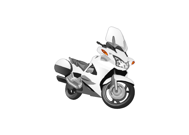
Motorcycle
Race car

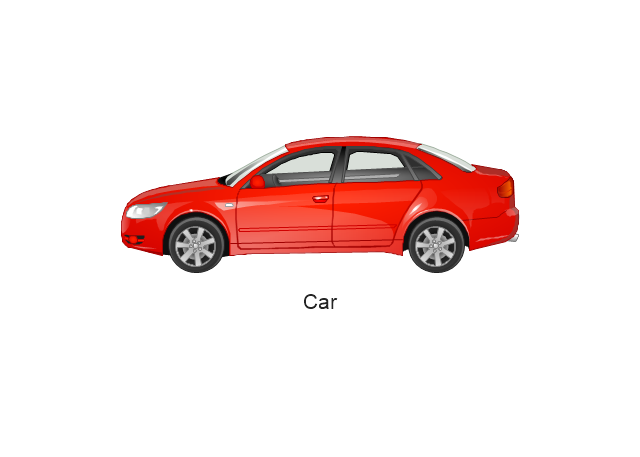
Car
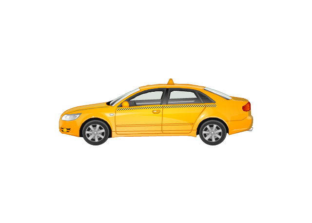
Taxi
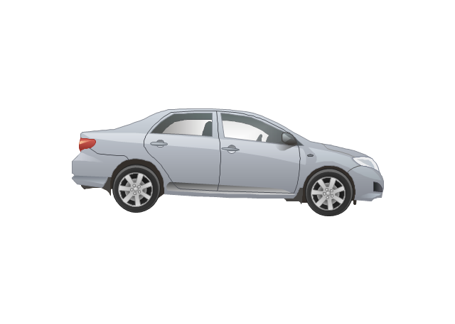
Sedan
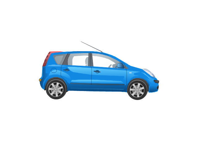
Hatchback
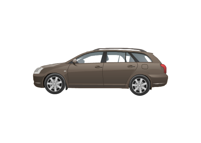
Estate car
4x4

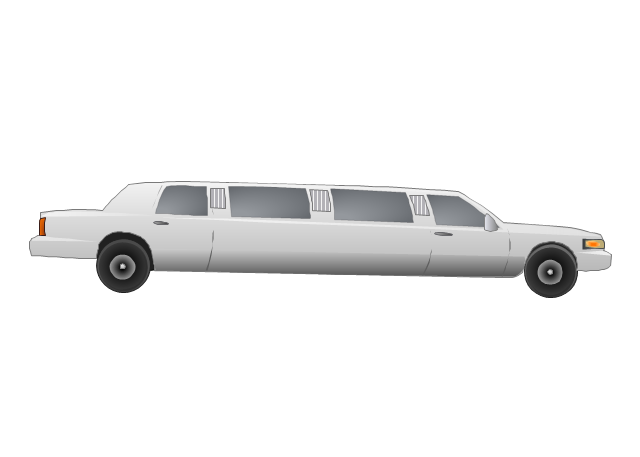
Limousine
Police car

Ambulance

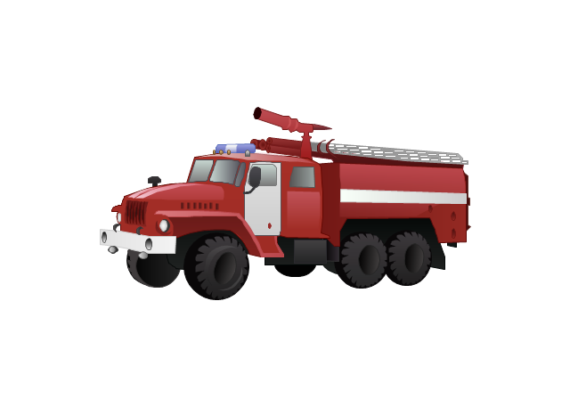
Fire apparatus
Wrecker

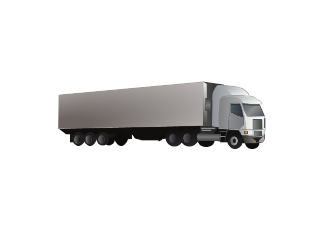
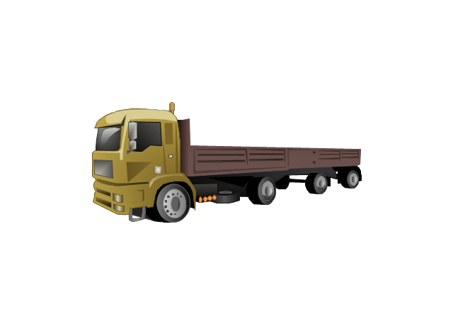
Semi truck

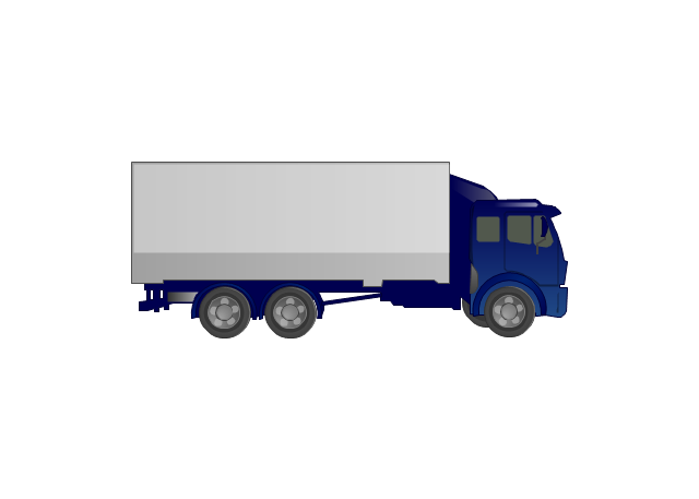
Truck
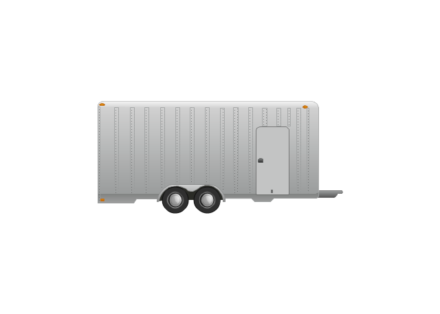
Trailer
Refrigeration Truck

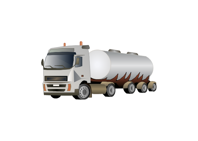
Petrol Tanker
Truck
Minibus

City Bus
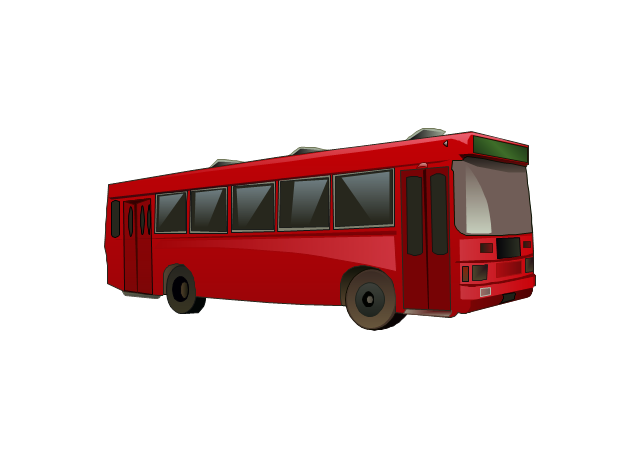
Bus
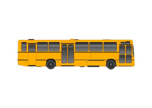
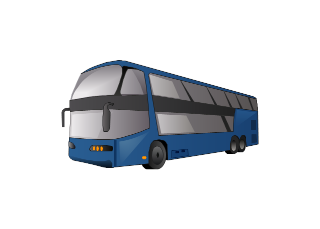
Sightseeing Bus

Double-decker Bus
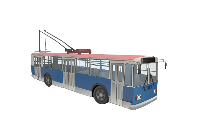
Trolleybus
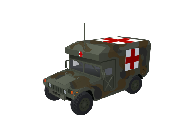
Military Ambulance
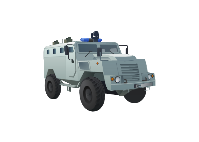
Armored police vehicle
First Aid Tent

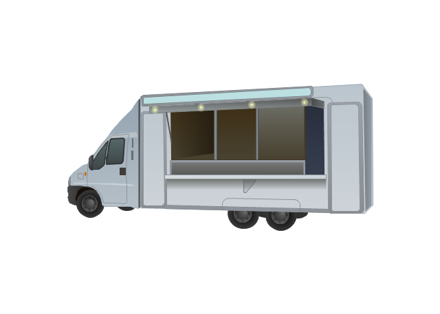
Catering Vehicle
Semi-trailer
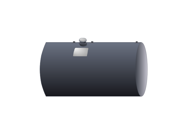
Fuel Tank
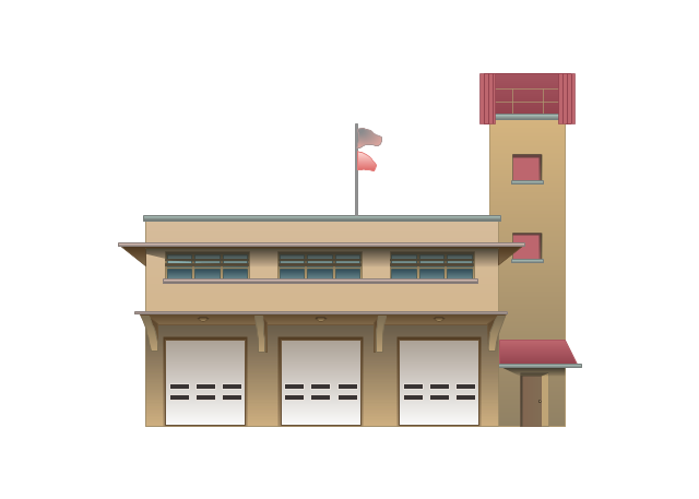
Fire Station
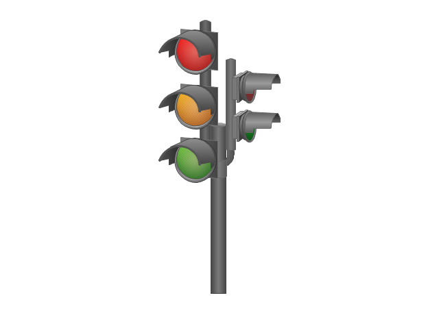
Signal Light
Walkie-Talkie

Lorry
B-Train
Taxi
Armored cash transport car

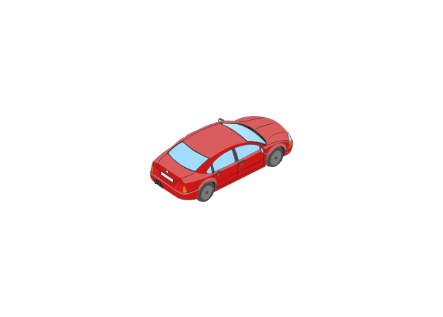
Car isometric
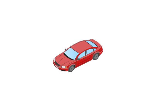
Car isometric
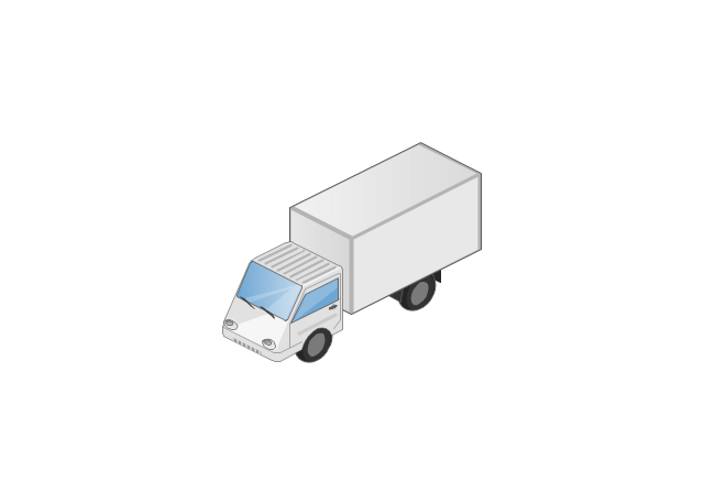
Box truck isometric
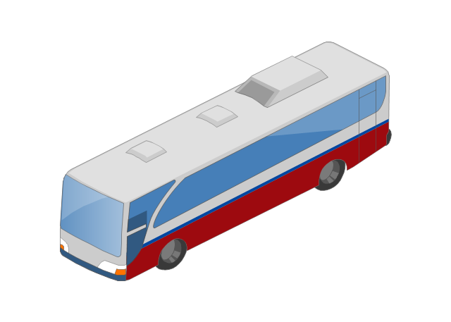
Bus isometric
Electrical Symbols — Maintenance

The vector stencils library "Audio" contains 91 audio, sound and music icons. Use it to design your audio, video and multimedia illustrations, presentations, web pages and infographics with ConceptDraw PRO diagramming and vector drawing software.
"Digital audio refers to technology that can be used to record, store, generate, manipulate, and reproduce sound using audio signals encoded in digital form. Following significant advances in digital audio technology during the 1970s, it rapidly replaced analog audio technology in most areas of sound production, sound engineering and telecommunications. Sound is converted to an analog electrical signal by a microphone, then an analog-to-digital converter (ADC), typically using pulse-code modulation, is used to convert it to a digital signal. A digital-to-analog converter performs the reverse process, converting a digital signal back into an analog signal, which can be converted to an audible sound by a loudspeaker. Digital audio systems may include compression, storage, processing and transmission components. Conversion to a digital format allows convenient manipulation, storage, transmission and retrieval of an audio signal." [Digital audio. Wikipedia]
The vector stencils library "Audio" is included in the Audio, Video, Media solution from the Illustration area of ConceptDraw Solution Park.
Audio wave

Mute

Volume

Music

Note

Notes

Music keys
Piano

Acoustic guitar
Guitar 1

Guitar 2

Electric guitar

Violin
Gramophone

Trumpet

Accordion
Microphone 1

Microphone 2

Microphone 3

Microphone 4

Microphone 5

Turn off microphone

Wire microphone

Mic 1

Mic 2

Karaoke

Singer

Megaphone 1

Megaphone 2

Loudspeaker

Bluetooth earpiece

Headset ear hook

Earphones 1

Earphones 2

Headset 1

Headset 2

Headset 3

Headphones 1

Headphones 2

Headphones 3

Headphones 4

Music player

Audio system

Stereo music system
Music system

Home theatre 1

Home theatre 2
Amplifier 1
Amplifier 2

Loudspeaker 1

Loudspeaker 2

Loudspeaker sound waves

Speaker 1

Speaker 2

Speaker box

Woofer

Woofer speaker

Subwoofer 1

Subwoofer 2

Stereo

Sound control

Vinyl

Audio cassette 1

Audio cassette 2

Cassette

Audio tape

Turntable

Record player

Cassette player

Tape player

Boombox 1

Boombox 2

Boombox 3

Portable radio

Radio set
Radio 1

Radio 2
Mixer
Equalizer 1

Equalizer 2
Equalizer 3

Volume adjuster
Volume control
DJ

Mixer table

Midi
Piano keyboard

Audio file

Music album

Audio cable 1

Audio cable 2

The vector stencils library "Analog and digital logic" contains 40 element symbols of logic (threshold) gates, bistable current switches, current controllers, regulators, electrical generators, and amplifiers.
Use it for drawing the digital and analog functions in electronic circuit diagrams and electrical schematics in the ConceptDraw PRO diagramming and vector drawing software extended with the Electrical Engineering solution from the Engineering area of ConceptDraw Solution Park.
www.conceptdraw.com/ solution-park/ engineering-electrical
Clock

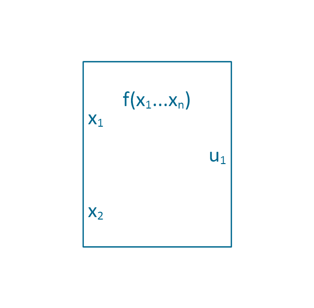
Function generator
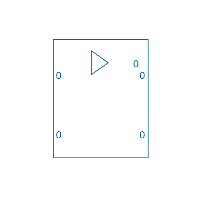
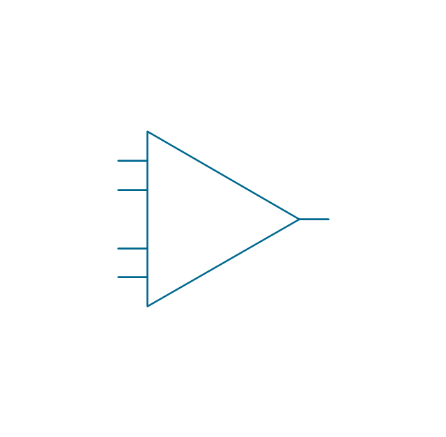
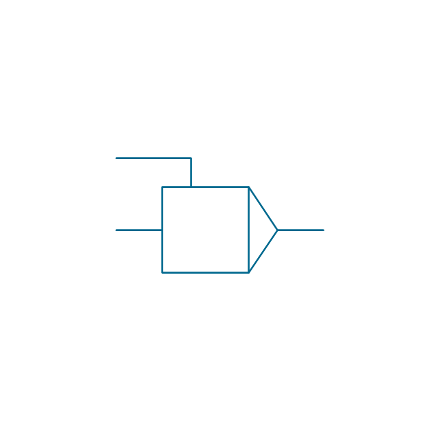
Amplifier
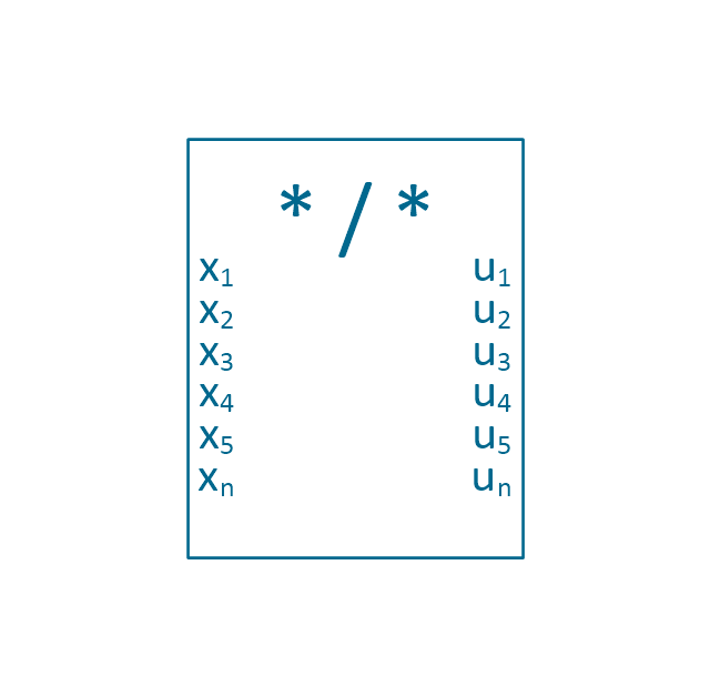
Converter
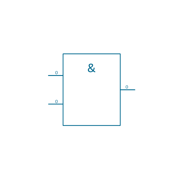
Logic gates
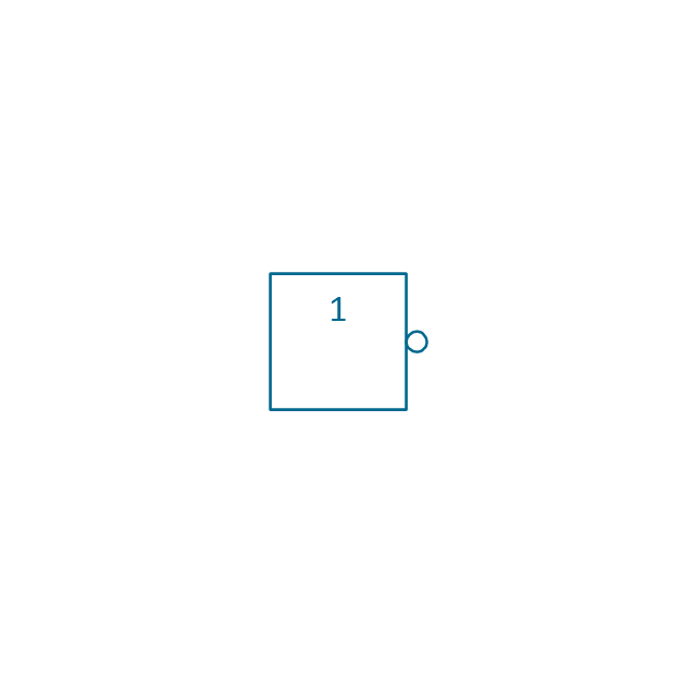
Inverter

Inverter 2
Buffer

Buffer 2

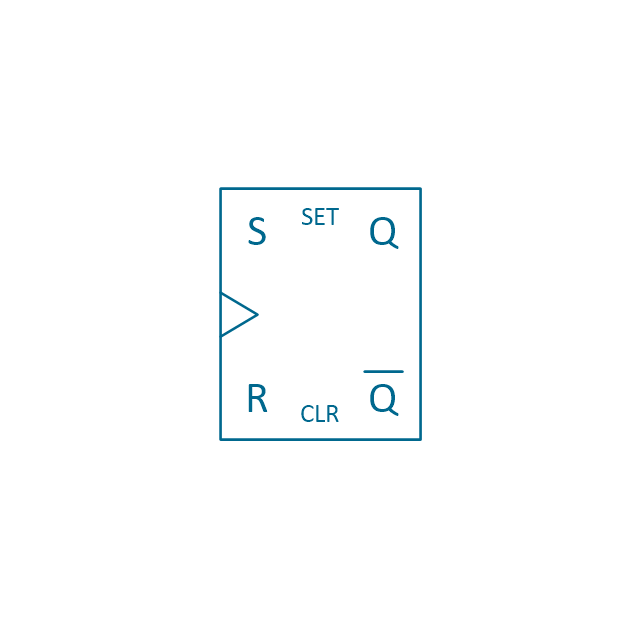
RS Flip-flop
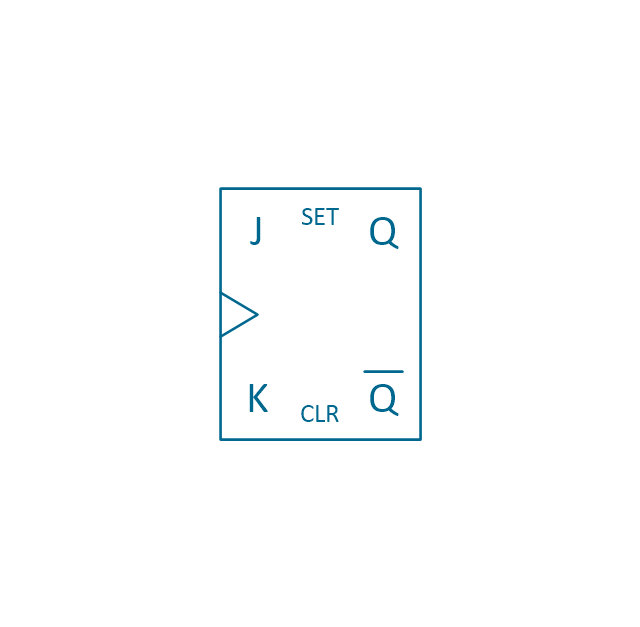
JK Flip-flop
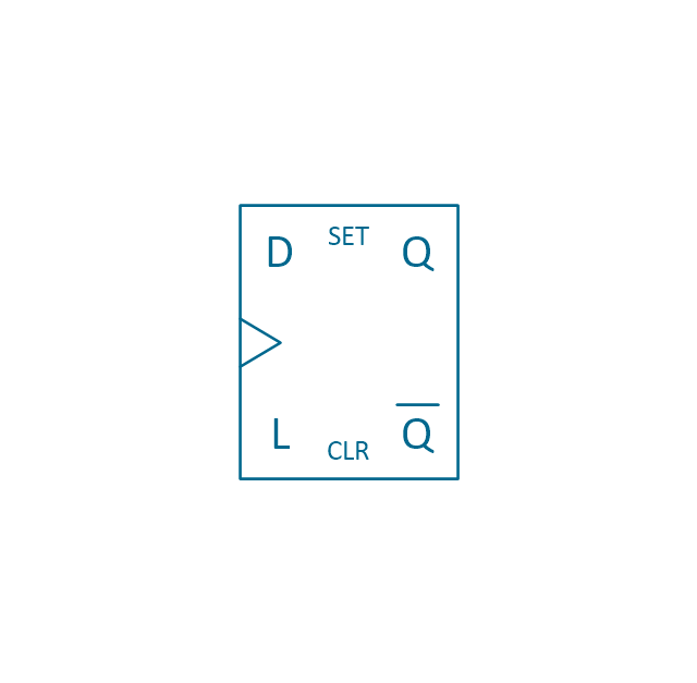
Latch Flip-flop
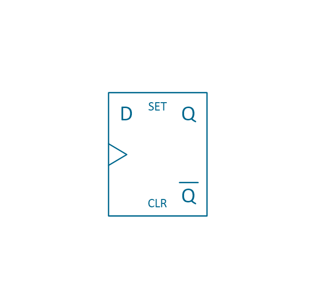
D Flip-flop
Analog symbol

Digital symbol

Negative logic dot

Potentiometer
Potentiometer 2
Positional servo
Piezoelectric crystal, 4 electrodes

Piezoelectric crystal, 3 electrodes

Piezoelectric crystal, 2 electrodes

I/O port bidirectional
I/O port unidirectional
Square signal

Sine wave signal
Sawtooth signal

Ramp signal
3 state data signal

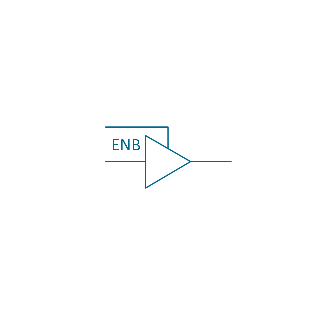
Three-state buffer
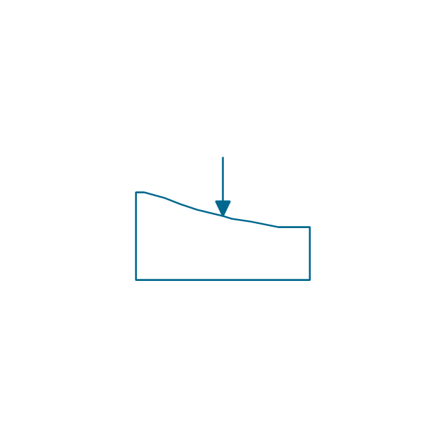
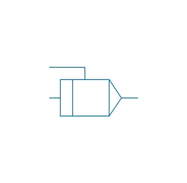
Integrator
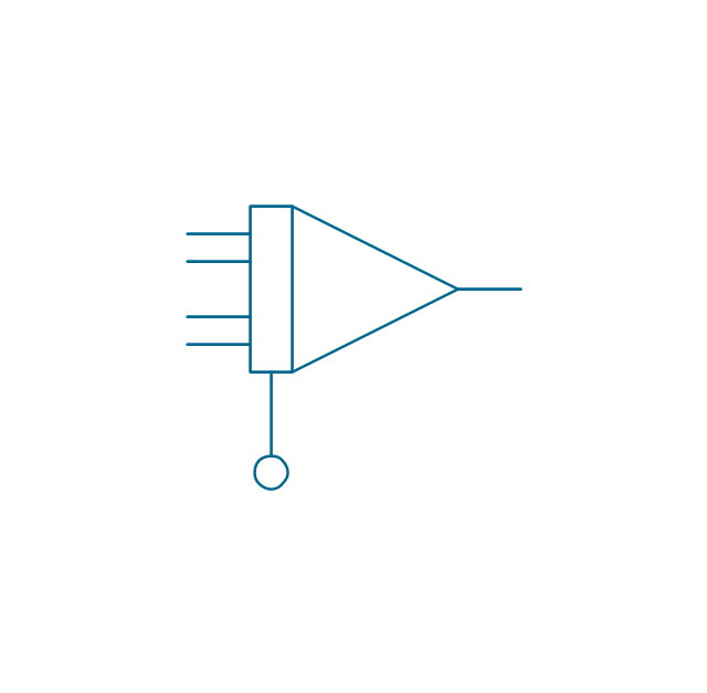
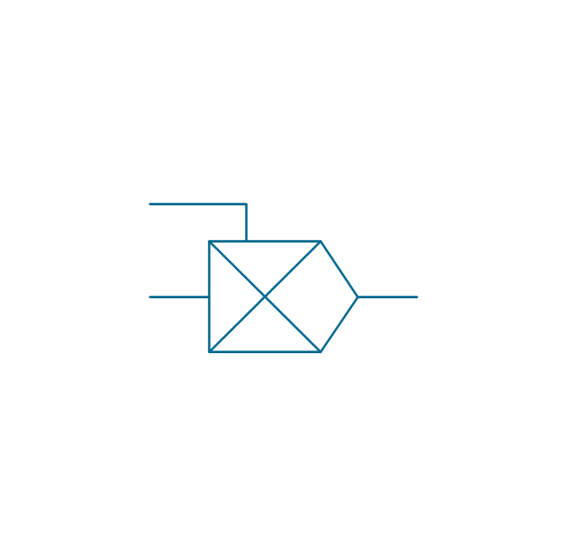
Summing amplifier
Multiplier
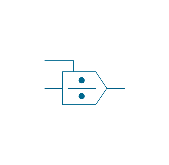
Divider
Function generator 2
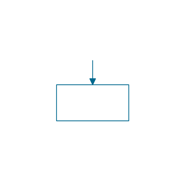
Generalized integrator
Operational amplifier

Operational amplifier 2
Switch point
Switch point 2

The vector stencils library "Switches and relays" contains 58 symbols of electrical contacts, switches, relays, circuit breakers, selectors, connectors, disconnect devices, switching circuits, current regulators, and thermostats for electrical devices.
"In electrical engineering, a switch is an electrical component that can break an electrical circuit, interrupting the current or diverting it from one conductor to another.
The most familiar form of switch is a manually operated electromechanical device with one or more sets of electrical contacts, which are connected to external circuits. Each set of contacts can be in one of two states: either "closed" meaning the contacts are touching and electricity can flow between them, or "open", meaning the contacts are separated and the switch is nonconducting. The mechanism actuating the transition between these two states (open or closed) can be either a "toggle" (flip switch for continuous "on" or "off") or "momentary" (push-for "on" or push-for "off") type.
A switch may be directly manipulated by a human as a control signal to a system, such as a computer keyboard button, or to control power flow in a circuit, such as a light switch. Automatically operated switches can be used to control the motions of machines, for example, to indicate that a garage door has reached its full open position or that a machine tool is in a position to accept another workpiece. Switches may be operated by process variables such as pressure, temperature, flow, current, voltage, and force, acting as sensors in a process and used to automatically control a system. ... A switch that is operated by another electrical circuit is called a relay. Large switches may be remotely operated by a motor drive mechanism. Some switches are used to isolate electric power from a system, providing a visible point of isolation that can be padlocked if necessary to prevent accidental operation of a machine during maintenance, or to prevent electric shock." [Switch. Wikipedia]
"A relay is an electrically operated switch. Many relays use an electromagnet to mechanically operate a switch, but other operating principles are also used, such as solid-state relays. Relays are used where it is necessary to control a circuit by a low-power signal (with complete electrical isolation between control and controlled circuits), or where several circuits must be controlled by one signal. The first relays were used in long distance telegraph circuits as amplifiers: they repeated the signal coming in from one circuit and re-transmitted it on another circuit. Relays were used extensively in telephone exchanges and early computers to perform logical operations.
A type of relay that can handle the high power required to directly control an electric motor or other loads is called a contactor. Solid-state relays control power circuits with no moving parts, instead using a semiconductor device to perform switching. Relays with calibrated operating characteristics and sometimes multiple operating coils are used to protect electrical circuits from overload or faults; in modern electric power systems these functions are performed by digital instruments still called "protective relays"." [Relay. Wikipedia]
The shapes example "Design elements - Switches and relays" was drawn using the ConceptDraw PRO diagramming and vector drawing software extended with the Electrical Engineering solution from the Engineering area of ConceptDraw Solution Park.
Switch and relay symbols

Ring Network Topology

The vector stencils library "Audio and video connectors" contains 94 symbols of audio and video connectors (TRS, TS, XLR, microphone, headphone, TOSLINK, DVI, VGA, DFP, S-Video, RCA, display port, HDMI, Thunderbolt, coaxial TV, F connector, MIDI) and device silhouettes.
Use these jacks and plugs clipart icons for drawing hook up diagrams.
"Audio connectors and video connectors are electrical connectors (or optical connectors) for carrying audio signal and video signal, of either analog or digital format. Analog A/ V connectors often use shielded cables to inhibit radio frequency interference (RFI) and noise." [Audio and video connector. Wikipedia]
"The existence of many different audio and video standards necessitates the definition of hardware interfaces, which define the physical characteristics of the connections between electrical equipment. This includes the types and numbers of wires required along with the strength and frequency of the signal. It also includes the physical design of the plugs and sockets.
An interface may define a connector that is used only by that interface (e.g., DVI) or may define a connector that is also used by another interface; for example, RCA connectors are defined both by the composite video and component video interfaces.
Audio connectors and video connectors are electrical connectors (or optical connectors) for carrying audio signal and video signal, of either analog or digital format. Analog A/ V connectors often use shielded cables to inhibit radio frequency interference (RFI) and noise.
Since both analog and digital signals are used with some styles of connectors, knowledge of the interface used is necessary for a successful transfer of signals. Some interface types use only a distinctive connector or family of connectors, to ensure compatibility. Especially with analog interfaces, physically interchangeable connectors may not carry compatible signals.
Some of these connectors, and other types of connectors, are also used at radio frequency (RF) to connect a radio or television receiver to an antenna or to a cable system..." [Audio and video interfaces and connectors. Wikipedia]
The clipart icons example "Design elements - Audio and video connectors" was created using the ConceptDraw PRO diagramming and vector drawing software extended with the Audio and Video Connectors solution from the Engineering area of ConceptDraw Solution Park.
Audio and video jacks and plugs

The vector stencils library "Cisco optical" contains 19 symbols of optical devices for drawing Cisco computer network diagrams.
"Fiber-optic communication is a method of transmitting information from one place to another by sending pulses of light through an optical fiber. The light forms an electromagnetic carrier wave that is modulated to carry information. ... Because of its advantages over electrical transmission, optical fibers have largely replaced copper wire communications in core networks in the developed world. Optical fiber is used by many telecommunications companies to transmit telephone signals, Internet communication, and cable television signals. ...
The process of communicating using fiber-optics involves the following basic steps: Creating the optical signal involving the use of a transmitter, relaying the signal along the fiber, ensuring that the signal does not become too distorted or weak, receiving the optical signal, and converting it into an electrical signal." [Fiber-optic communication. Wikipedia]
The symbols example "Cisco optical - Vector stencils library" was created using the ConceptDraw PRO diagramming and vector drawing software extended with the Cisco Network Diagrams solution from the Computer and Networks area of ConceptDraw Solution Park.
www.conceptdraw.com/ solution-park/ computer-networks-cisco
Automatic Protection Switching (APS)
-cisco-optical---vector-stencils-library.png--diagram-flowchart-example.png)
Channelized pipe

Concatenated payload

Optical cross-connect

WDM

Optical fiber

ONS 15104

SONET MUX

Optical amplifier

Digitall cross-connect

Optical services router

Cisco 10700

Optical transport

Wide Area Application Engine (WAE)
-cisco-optical---vector-stencils-library.png--diagram-flowchart-example.png)
Protected optical

Unprotected optical

Metro 1500

ONS 15500

Pipe

- Traffic Signal In Road Png
- Network Topologies | Red Wifi Signal Low Icon Png
- Radio Signal Png
- Status Bar Signal Png
- Signal Status Bar Png
- Good Network Signal Png
- Car Signal Png
- Png Road Signal Light
- Red Signal Wave Vector Png
- Wifi Strength Png
- Signal Icon Png
- Road transport - Vector stencils library | Traffic Cars Icon Type Png
- Audio - Vector stencils library | Microphone 2d Png
- Noise Symbol Png
- Digital Piano Icon Png
- Android No Wifi Signal
- Send Signal
- Networking Cctv Png
- Iphone Battery Png
- Vector Sound System Png