Local area network (LAN). Computer and Network Examples
 diagram")

Metropolitan area networks (MAN). Computer and Network Examples
. Computer and Network Examples")
Campus Area Networks (CAN). Computer and Network Examples

Network Diagram Software Enterprise Private Network
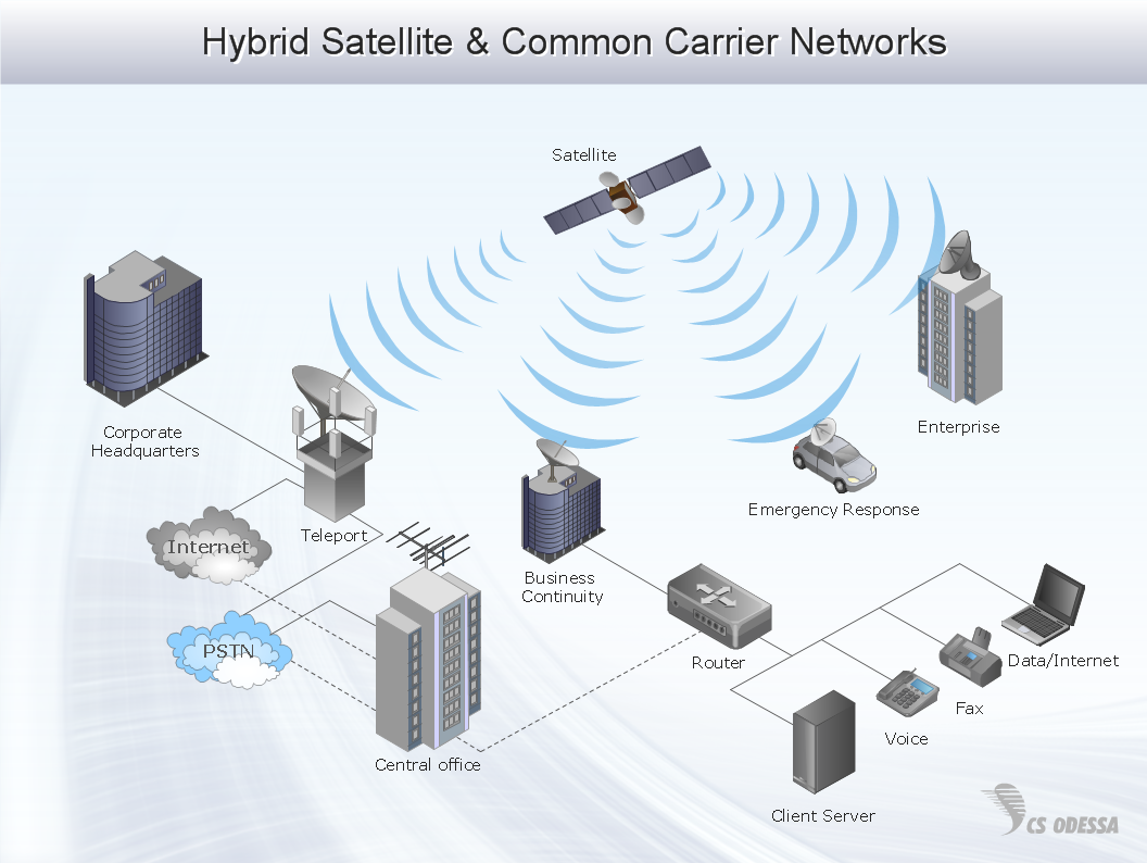
 Wireless Networks
The Wireless Networks Solution extends ConceptDraw DIAGRAM software with professional diagramming tools, set of wireless network diagram templates and samples, comprehensive library of wireless communications and WLAN objects to help network engineers and designers efficiently design and create Wireless network diagrams that illustrate wireless networks of any speed and complexity, and help to identify all required equipment for construction and updating wireless networks, and calculating their costs.
"The Ethernet physical layer is the physical layer component of the Ethernet family of computer network standards.
The Ethernet physical layer evolved over a considerable time span and encompasses quite a few physical media interfaces and several magnitudes of speed. The speed ranges from 1 Mbit/ s to 100 Gbit/ s, while the physical medium can range from bulky coaxial cable to twisted pair and optical fiber. In general, network protocol stack software will work similarly on all physical layers.
10-gigabit Ethernet was already used in both enterprise and carrier networks by 2007, with 40 Gbit/ s and 100 Gbit/ s Ethernet ratified. ...
Many Ethernet adapters and switch ports support multiple speeds, using autonegotiation to set the speed and duplex for the best values supported by both connected devices. If auto-negotiation fails, a multiple-speed device will sense the speed used by its partner, but will assume half-duplex. A 10/ 100 Ethernet port supports 10BASE-T and 100BASE-TX. A 10/ 100/ 1000 Ethernet port supports 10BASE-T, 100BASE-TX, and 1000BASE-T." [Ethernet physical layer. Wikipedia]
The LAN equipment and cabling layout floorplan example "Ethernet local area network layout floor plan" was created using the ConceptDraw PRO diagramming and vector drawing software extended with the Network Layout Floor Plans solution from the Computer and Networks area of ConceptDraw Solution Park.
Ethernet LAN layout floorplan

Wide area network (WAN) topology. Computer and Network Examples

Network Glossary Definition

Network Security Devices

 Network Layout Floor Plans
Network Layout Floor Plans solution extends ConceptDraw DIAGRAM software functionality with powerful tools for quick and efficient documentation the network equipment and displaying its location on the professionally designed Network Layout Floor Plans. Never before creation of Network Layout Floor Plans, Network Communication Plans, Network Topologies Plans and Network Topology Maps was not so easy, convenient and fast as with predesigned templates, samples, examples and comprehensive set of vector design elements included to the Network Layout Floor Plans solution. All listed types of plans will be a good support for the future correct cabling and installation of network equipment.
- Roaming wireless local area network diagram | Long- range Wi-Fi ...
- Home area networks (HAN). Computer and Network Examples ...
- Long- range Wi-Fi network diagram | Wireless networks - Vector ...
- Metropolitan Area Network Range
- Ethernet network | Long- range Wi-Fi network diagram | Network ...
- Long- range Wi-Fi network diagram | Network Layout Floor Plans ...
- Computer and Networks Area | Lan Area Network Range Sketch ...
- Network Layout Floor Plans | Local area network ( LAN ). Computer ...
- Wireless access point - Network diagram | Computer network ...
- Local area network ( LAN ). Computer and Network Examples ...