The vector stencils library "Cable TV" contains 64 symbols of cable TV network equipment.
Use these shapes for drawing CATV system design floor plans, network topology diagrams, wiring diagrams and cabling layout schemes in the ConceptDraw PRO diagramming and vector drawing software.
The vector stencils library "Cable TV" is included in the Electric and Telecom Plans solution from the Building Plans area of ConceptDraw Solution Park.
Output Directional Tap 1

Output Directional Tap 2

Output Directional Tap 3

Output Directional Tap 4

Output Directional Tap 5

2-way Splitter

3-way Splitter

4-way Splitter

AC Power Block

Bond

Down Guy

Building Guy and Anchor

Rock Guy with Anchor

Down Guy with Anchor

Pole-to-Pole Guy

Sidewalk Down Guy with Anchor

Sidewalk Down Guy

Slack Span Messenger Wire

Tensioned Messenger Wire w/out cable

Tensioned Messenger Wire

Ground

Joint Usage (Power & Telephone Pole)
-cable-tv---vector-stencils-library.png--diagram-flowchart-example.png)
Joint Usgae Pole with Transformer

Strut

Tree Guy with Anchor

Push Brace (smaller pole in actual relative position)
-cable-tv---vector-stencils-library.png--diagram-flowchart-example.png)
Extension Arm

Built CATV Pole

Proposed CATV Pole

Directional Tap 1

Directional Tap 2

Manhole

Telephone Pole

Riser Pole

Vault Handheld

Fixed Equalizer

Fixed Flat Attenuators

Other Supporting Structures

Pedestal - Underground Routing

Power Pole

Direct Buried Underground Routing

Duct Line Underground Routing

Line Terminations

2-Way Optical Splice Location

3-Way Optical Splice Location

4-Way Optical Splice Location

> 4-Way Optical Splice Location

Optical Amplifier

Cable AC Power Combiner

Optical Fiber Cable

Optical Connector

Wavelength Demultiplexer

Wavelength Multiplexer

Optical Transmitter

Optical Transmitter

Optical Node

Optical Splitter

Headend (Signal Processing)
-cable-tv---vector-stencils-library.png--diagram-flowchart-example.png)
Node

Primary Hub

Secondary Hub

Coaxial Splice

Power Supply

Variable Equalizer

The vector stencils library "Cable TV" contains 64 symbols of cable TV network equipment.
Use these shapes for drawing CATV system design floor plans, network topology diagrams, wiring diagrams and cabling layout schemes in the ConceptDraw PRO diagramming and vector drawing software.
The vector stencils library "Cable TV" is included in the Electric and Telecom Plans solution from the Building Plans area of ConceptDraw Solution Park.
Use these shapes for drawing CATV system design floor plans, network topology diagrams, wiring diagrams and cabling layout schemes in the ConceptDraw PRO diagramming and vector drawing software.
The vector stencils library "Cable TV" is included in the Electric and Telecom Plans solution from the Building Plans area of ConceptDraw Solution Park.
Output Directional Tap 1
Output Directional Tap 2
Output Directional Tap 3
Output Directional Tap 4
Output Directional Tap 5
2-way Splitter
3-way Splitter
4-way Splitter
AC Power Block
Bond
Down Guy
Building Guy and Anchor
Rock Guy with Anchor
Down Guy with Anchor
Pole-to-Pole Guy
Sidewalk Down Guy with Anchor
Sidewalk Down Guy
Slack Span Messenger Wire
Tensioned Messenger Wire w/out cable
Tensioned Messenger Wire
Ground
Joint Usage (Power & Telephone Pole)
Joint Usgae Pole with Transformer
Strut
Tree Guy with Anchor
Push Brace (smaller pole in actual relative position)
Extension Arm
Built CATV Pole
Proposed CATV Pole
Directional Tap 1
Directional Tap 2
Manhole
Telephone Pole
Riser Pole
Vault Handheld
Fixed Equalizer
Fixed Flat Attenuators
Other Supporting Structures
Pedestal - Underground Routing
Power Pole
Direct Buried Underground Routing
Duct Line Underground Routing
Line Terminations
2-Way Optical Splice Location
3-Way Optical Splice Location
4-Way Optical Splice Location
> 4-Way Optical Splice Location
Optical Amplifier
Cable AC Power Combiner
Optical Fiber Cable
Optical Connector
Wavelength Demultiplexer
Wavelength Multiplexer
Optical Transmitter
Optical Transmitter
Optical Node
Optical Splitter
Headend (Signal Processing)
Node
Primary Hub
Secondary Hub
Coaxial Splice
Power Supply
Variable Equalizer
 Engineering
This solution extends ConceptDraw DIAGRAM.4 with the ability to visualize industrial systems in electronics, electrical, chemical, process, and mechanical engineering.
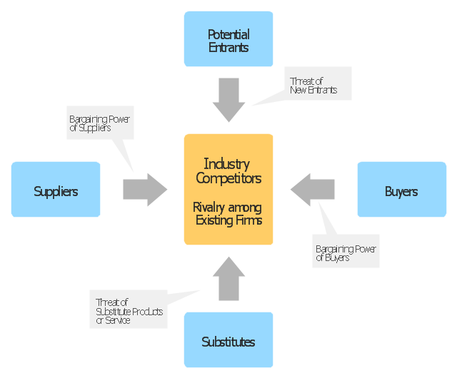
"Porter five forces analysis is a framework for industry analysis and business strategy development. It draws upon industrial organization (IO) economics to derive five forces that determine the competitive intensity and therefore attractiveness of a market. Attractiveness in this context refers to the overall industry profitability. An "unattractive" industry is one in which the combination of these five forces acts to drive down overall profitability. A very unattractive industry would be one approaching "pure competition", in which available profits for all firms are driven to normal profit.
Three of Porter's five forces refer to competition from external sources. The remainder are internal threats.
Porter referred to these forces as the micro environment, to contrast it with the more general term macro environment. They consist of those forces close to a company that affect its ability to serve its customers and make a profit. A change in any of the forces normally requires a business unit to re-assess the marketplace given the overall change in industry information. The overall industry attractiveness does not imply that every firm in the industry will return the same profitability. Firms are able to apply their core competencies, business model or network to achieve a profit above the industry average. A clear example of this is the airline industry. As an industry, profitability is low and yet individual companies, by applying unique business models, have been able to make a return in excess of the industry average.
Porter's five forces include - three forces from 'horizontal' competition: the threat of substitute products or services, the threat of established rivals, and the threat of new entrants; and two forces from 'vertical' competition: the bargaining power of suppliers and the bargaining power of customers.
This five forces analysis, is just one part of the complete Porter strategic models. The other elements are the value chain and the generic strategies." [Porter five forces analysis. Wikipedia]
The block diagram example "Porter's five forces model" was created using the ConceptDraw PRO diagramming and vector drawing software extended with the Block Diagrams solution from the area "What is a Diagram" of ConceptDraw Solution Park.
Block diagram
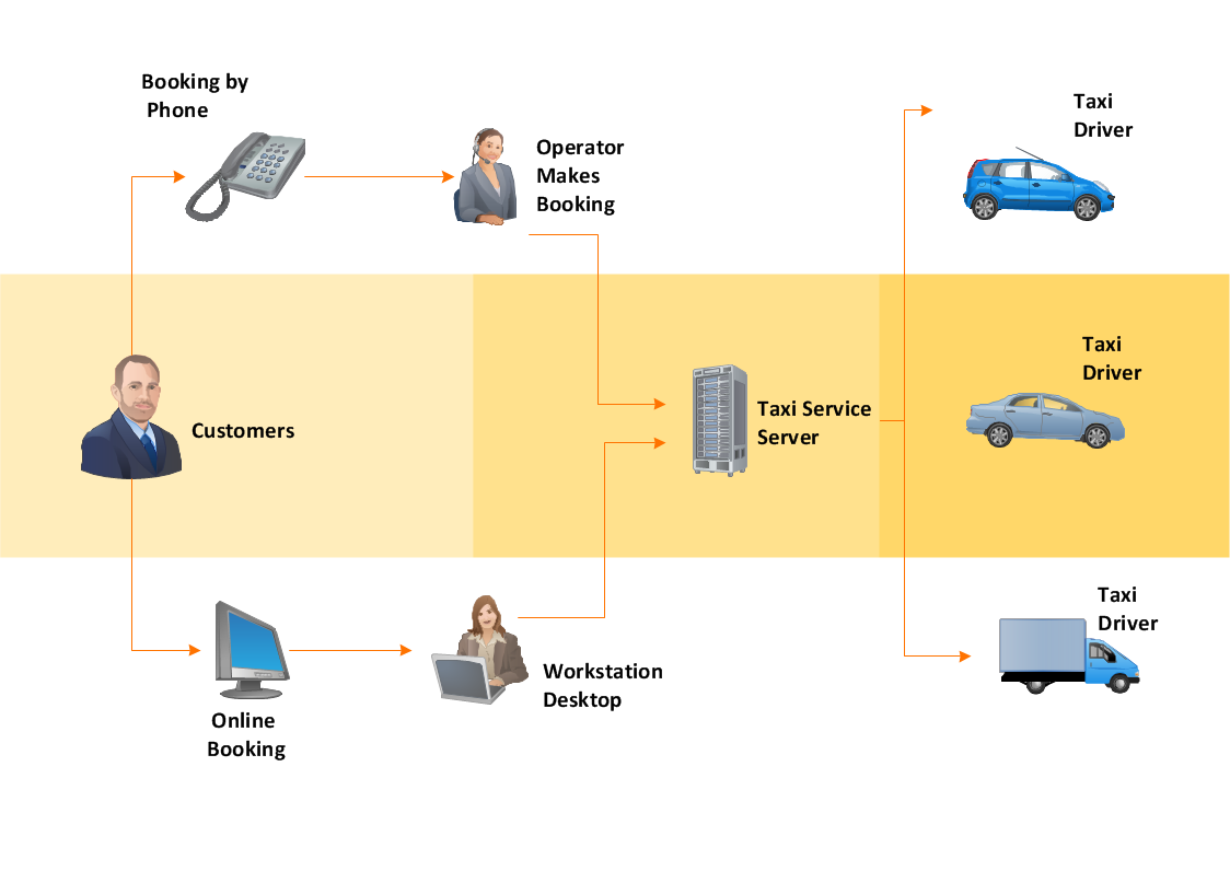
Workflow Diagram
HelpDesk
How to Add a Block Diagram to a PowerPoint Presentation

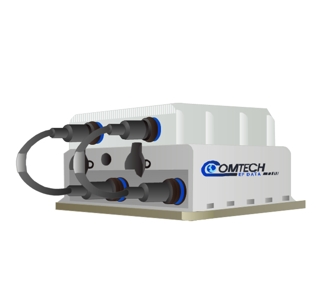
The vector stencils library "Comtech" contains 9 icons of Comtech devices for drawing computer network diagrams and telecommunication equipment layouts.
"Comtech EF Data Corporation ... communication solutions encompass Advanced VSAT Solutions, Modems, RAN & WAN Optimization, Network & Bandwidth Management, RF Products ... for fixed and mobile/ transportable satellite-based applications." [comtechefdata.com]
The clip art example "Comtech - Vector stencils library" was created using the ConceptDraw PRO diagramming and vector drawing software extended with the Telecommunication Network Diagrams solution from the Computer and Networks area of ConceptDraw Solution Park.
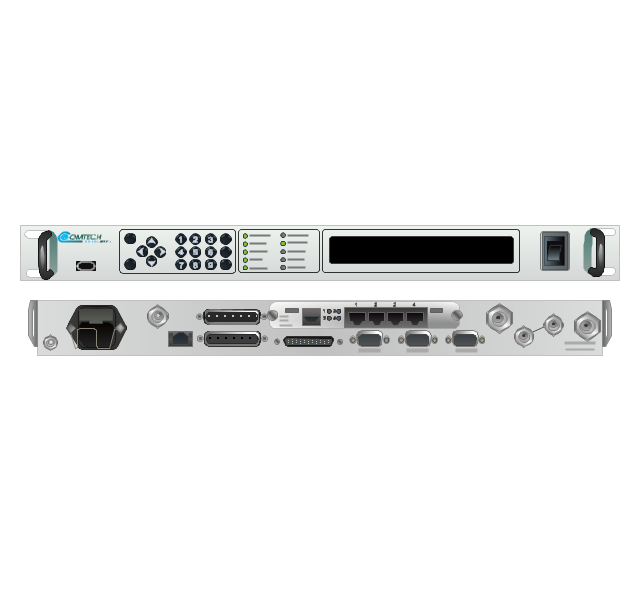
CDD-562L & CDD-562LEN dual IP demodulator
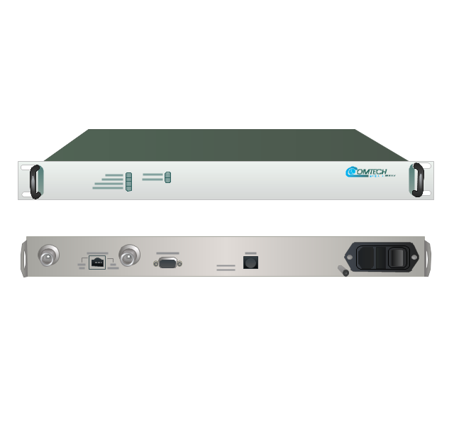
CDM-700G high-speed satellite modem
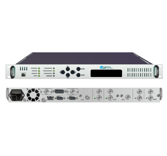
CDM-710G high-speed satellite modem
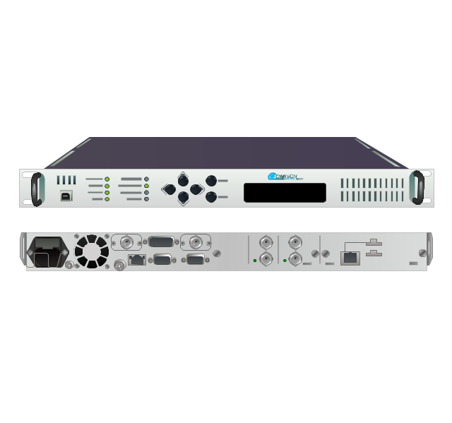
SLM-5650A satellite modem
UT-4505 series up converters
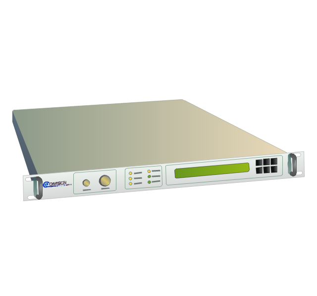
LPOD C- or Ku-band block up converters
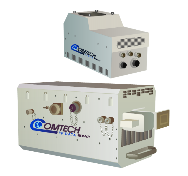
MBT-4000/ MBT-4000B outdoor multi-band RF transceiver
High-Power Outdoor C-, X- & Ku-band outdoor amplifier (HPOD)
-comtech---vector-stencils-library.png--diagram-flowchart-example.png)
Indoor solid state power amplifiers (SSPA)
-comtech---vector-stencils-library.png--diagram-flowchart-example.png)
Business Diagram Software


The vector stencils library "Comtech" contains 9 icons of Comtech devices for drawing computer network diagrams and telecommunication equipment layouts.
"Comtech EF Data Corporation ... communication solutions encompass Advanced VSAT Solutions, Modems, RAN & WAN Optimization, Network & Bandwidth Management, RF Products ... for fixed and mobile/ transportable satellite-based applications." [comtechefdata.com]
The clip art example "Comtech - Vector stencils library" was created using the ConceptDraw PRO diagramming and vector drawing software extended with the Telecommunication Network Diagrams solution from the Computer and Networks area of ConceptDraw Solution Park.
"Comtech EF Data Corporation ... communication solutions encompass Advanced VSAT Solutions, Modems, RAN & WAN Optimization, Network & Bandwidth Management, RF Products ... for fixed and mobile/ transportable satellite-based applications." [comtechefdata.com]
The clip art example "Comtech - Vector stencils library" was created using the ConceptDraw PRO diagramming and vector drawing software extended with the Telecommunication Network Diagrams solution from the Computer and Networks area of ConceptDraw Solution Park.
CDD-562L & CDD-562LEN dual IP demodulator
CDM-700G high-speed satellite modem
CDM-710G high-speed satellite modem
SLM-5650A satellite modem
UT-4505 series up converters
LPOD C- or Ku-band block up converters
MBT-4000/ MBT-4000B outdoor multi-band RF transceiver
High-Power Outdoor C-, X- & Ku-band outdoor amplifier (HPOD)
Indoor solid state power amplifiers (SSPA)
 Plant Layout Plans
Plant Layout Plans solution can be used for power plant design and plant layout design, for making the needed building plant plans and plant layouts looking professionally good. Having the newest plant layout software, the plant design solutions and in particular the ConceptDraw’s Plant Layout Plans solution, including the pre-made templates, examples of the plant layout plans, and the stencil libraries with the design elements, the architects, electricians, interior designers, builders, telecommunications managers, plant design engineers, and other technicians can use them to create the professionally looking drawings within only a few minutes.
The vector stencils library "Transistors" contains 30 symbols of transistors drawing electronic schematics and circuit diagrams.
"A transistor is a semiconductor device used to amplify and switch electronic signals and electrical power. It is composed of semiconductor material with at least three terminals for connection to an external circuit. A voltage or current applied to one pair of the transistor's terminals changes the current through another pair of terminals. Because the controlled (output) power can be higher than the controlling (input) power, a transistor can amplify a signal. Today, some transistors are packaged individually, but many more are found embedded in integrated circuits.
The transistor is the fundamental building block of modern electronic devices, and is ubiquitous in modern electronic systems. ...
Transistors are categorized by:
(1) Semiconductor material...: the metalloids germanium ... and silicon ... in amorphous, polycrystalline and monocrystalline form; the compounds gallium arsenide ... and silicon carbide ..., the alloy silicon-germanium ..., the allotrope of carbon graphene ...
(2) Structure: BJT, JFET, IGFET (MOSFET), insulated-gate bipolar transistor, "other types"
(3) Electrical polarity (positive and negative): n–p–n, p–n–p (BJTs); n-channel, p-channel (FETs)
(4) Maximum power rating: low, medium, high
(5) Maximum operating frequency: low, medium, high, radio (RF), microwave frequency...
(6) Application: switch, general purpose, audio, high voltage, super-beta, matched pair
(7) Physical packaging: through-hole metal, through-hole plastic, surface mount, ball grid array, power modules...
(8) Amplification factor..." [Transistor. Wikipedia]
The shapes example "Design elements - Transistors" was drawn using the ConceptDraw PRO diagramming and vector drawing software extended with the Electrical Engineering solution from the Engineering area of ConceptDraw Solution Park.
Transistor symbols

Technical Drawing Software

 Electrical Engineering
This solution extends ConceptDraw DIAGRAM.9.5 (or later) with electrical engineering samples, electrical schematic symbols, electrical diagram symbols, templates and libraries of design elements, to help you design electrical schematics, digital and analog
 Mechanical Engineering
This solution extends ConceptDraw DIAGRAM.9 mechanical drawing software (or later) with samples of mechanical drawing symbols, templates and libraries of design elements, for help when drafting mechanical engineering drawings, or parts, assembly, pneumatic,
Technical Drawing Software

- AC Power Block
- Design elements - Cable TV (CATV) | Cable TV - Vector stencils ...
- Block Diagram Symbols Amplifier
- Cable TV - Vector stencils library | Draw The Block Digram Of Cable ...
- Block diagram - Automotive HVAC system | HVAC Plans | Cable TV ...
- Block Diagram Topology
- Cable TV - Vector stencils library | Power sources - Vector stencils ...
- Regional cable head-end diagram | Cable TV - Vector stencils ...
- Block Of Flats Building Plans
- Cable TV - Vector stencils library
- Design elements - Power sources | Electrical Drawing Software ...
- Cable TV - Vector stencils library | Interior Design Site Plan - Design ...
- Design elements - Power sources | Power sources - Vector stencils ...
- Power socket outlet layout | Plant Layout Plans | Cafe electrical floor ...
- Interior Design Site Plan - Design Elements | Site Plans | Cable TV ...
- Power socket outlet layout | Design elements - Fluid power ...
- Block Diagrams
- Power socket outlet layout | Design elements - Outlets | How To use ...
- Cable TV - Vector stencils library | Network layout floorplan - Vector ...