The vector stencils library "Cable TV" contains 64 symbols of cable TV network equipment.
Use these shapes for drawing CATV system design floor plans, network topology diagrams, wiring diagrams and cabling layout schemes in the ConceptDraw PRO diagramming and vector drawing software.
The vector stencils library "Cable TV" is included in the Electric and Telecom Plans solution from the Building Plans area of ConceptDraw Solution Park.
Output Directional Tap 1

Output Directional Tap 2

Output Directional Tap 3

Output Directional Tap 4

Output Directional Tap 5

2-way Splitter

3-way Splitter

4-way Splitter

AC Power Block

Bond

Down Guy

Building Guy and Anchor

Rock Guy with Anchor

Down Guy with Anchor

Pole-to-Pole Guy

Sidewalk Down Guy with Anchor

Sidewalk Down Guy

Slack Span Messenger Wire

Tensioned Messenger Wire w/out cable

Tensioned Messenger Wire

Ground

Joint Usage (Power & Telephone Pole)
-cable-tv---vector-stencils-library.png--diagram-flowchart-example.png)
Joint Usgae Pole with Transformer

Strut

Tree Guy with Anchor

Push Brace (smaller pole in actual relative position)
-cable-tv---vector-stencils-library.png--diagram-flowchart-example.png)
Extension Arm

Built CATV Pole

Proposed CATV Pole

Directional Tap 1

Directional Tap 2

Manhole

Telephone Pole

Riser Pole

Vault Handheld

Fixed Equalizer

Fixed Flat Attenuators

Other Supporting Structures

Pedestal - Underground Routing

Power Pole

Direct Buried Underground Routing

Duct Line Underground Routing

Line Terminations

2-Way Optical Splice Location

3-Way Optical Splice Location

4-Way Optical Splice Location

> 4-Way Optical Splice Location

Optical Amplifier

Cable AC Power Combiner

Optical Fiber Cable

Optical Connector

Wavelength Demultiplexer

Wavelength Multiplexer

Optical Transmitter

Optical Transmitter

Optical Node

Optical Splitter

Headend (Signal Processing)
-cable-tv---vector-stencils-library.png--diagram-flowchart-example.png)
Node

Primary Hub

Secondary Hub

Coaxial Splice

Power Supply

Variable Equalizer

The vector stencils library "Network layout floorplan" contain 34 symbol icons for drawing computer network floor plans, communication equipment layouts, and structured cabling diagrams.
"Structured cabling is building or campus telecommunications cabling infrastructure that consists of a number of standardized smaller elements (hence structured) called subsystems. ...
Structured cabling design and installation is governed by a set of standards that specify wiring data centers, offices, and apartment buildings for data or voice communications using various kinds of cable, most commonly category 5e (CAT-5e), category 6 (CAT-6), and fibre optic cabling and modular connectors. These standards define how to lay the cabling in various topologies in order to meet the needs of the customer, typically using a central patch panel (which is normally 19 inch rack-mounted), from where each modular connection can be used as needed. Each outlet is then patched into a network switch (normally also rack-mounted) for network use or into an IP or PBX (private branch exchange) telephone system patch panel." [Structured cabling. Wikipedia]
The design elements example "Network layout floorplan - Vector stencils library" was created using the ConceptDraw PRO diagramming and vector drawing software extended with the Network Layout Floor Plans solution from the Computer and Networks area of ConceptDraw Solution Park.
PC

Scanner

Switch

Router

Modem

Hub

Rack Mount

Printer

Floor Mounted Outlet

Single Outlet

Duplex Outlet

Direct bus cable

Tops or bottoms bus cable

Side to side bus cable

Multi-tree bus cable

Bottom to side bus cable

Sides bus cable

Door

Door, threshold

Door, stop

Door, stop, threshold

Door, frame

Door, frame, threshold

Door, frame, stop

Door, frame, stop, threshold

Window

Window, sill

Window, sash

Window, sash, sill

Window, frame

Window, frame, sill

Window, frame, sash

Window, frame, sash, sill

The design elements library "Cable TV" contains 64 symbols of CATV network equipment.
"Cable television is a system of distributing television programs to subscribers via radio frequency (RF) signals transmitted through coaxial cables or light pulses through fiber-optic cables. This contrasts with traditional broadcast television (terrestrial television) in which the television signal is transmitted over the air by radio waves and received by a television antenna attached to the television. FM radio programming, high-speed Internet, telephone service, and similar non-television services may also be provided through these cables.
The abbreviation CATV is often used for cable television." [Cable television. Wikipedia]
Use the shapes library "Cable TV" to draw CATV system design floor plans, network topology diagrams, wiring diagrams and cabling layout schemes using the ConceptDraw PRO diagramming and vector drawing software.
The vector stencils library "Cable TV" is included in the Electric and Telecom Plans solution from the Building Plans area of ConceptDraw Solution Park.
Cable TV symbols
.png--diagram-flowchart-example.png)
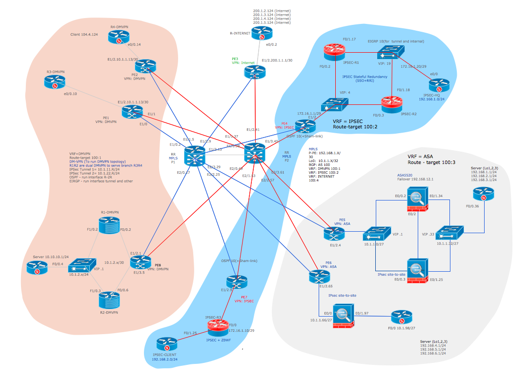
Cisco Network Design. Cisco icons, shapes, stencils, symbols and design elements

Network Icon

Cisco Icon
 Network Layout Floor Plans
Network Layout Floor Plans solution extends ConceptDraw DIAGRAM software functionality with powerful tools for quick and efficient documentation the network equipment and displaying its location on the professionally designed Network Layout Floor Plans. Never before creation of Network Layout Floor Plans, Network Communication Plans, Network Topologies Plans and Network Topology Maps was not so easy, convenient and fast as with predesigned templates, samples, examples and comprehensive set of vector design elements included to the Network Layout Floor Plans solution. All listed types of plans will be a good support for the future correct cabling and installation of network equipment.
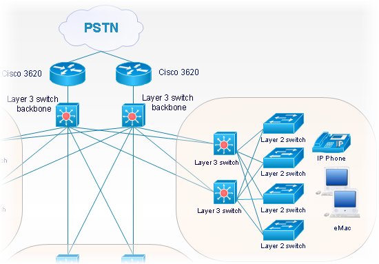
Local area network (LAN). Computer and Network Examples
 diagram")

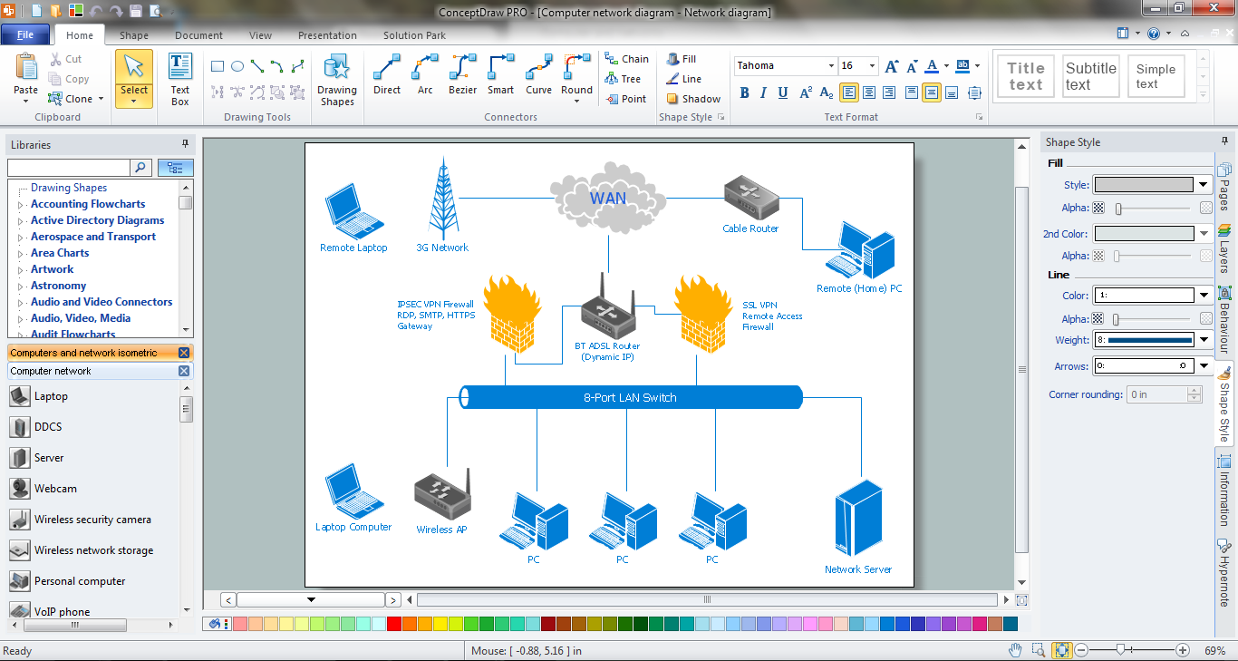
ConceptDraw DIAGRAM Network Diagram Tool


Network Icons
The vector stencils library "Cisco routers" contains 27 symbols of routers for drawing Cisco computer network diagrams.
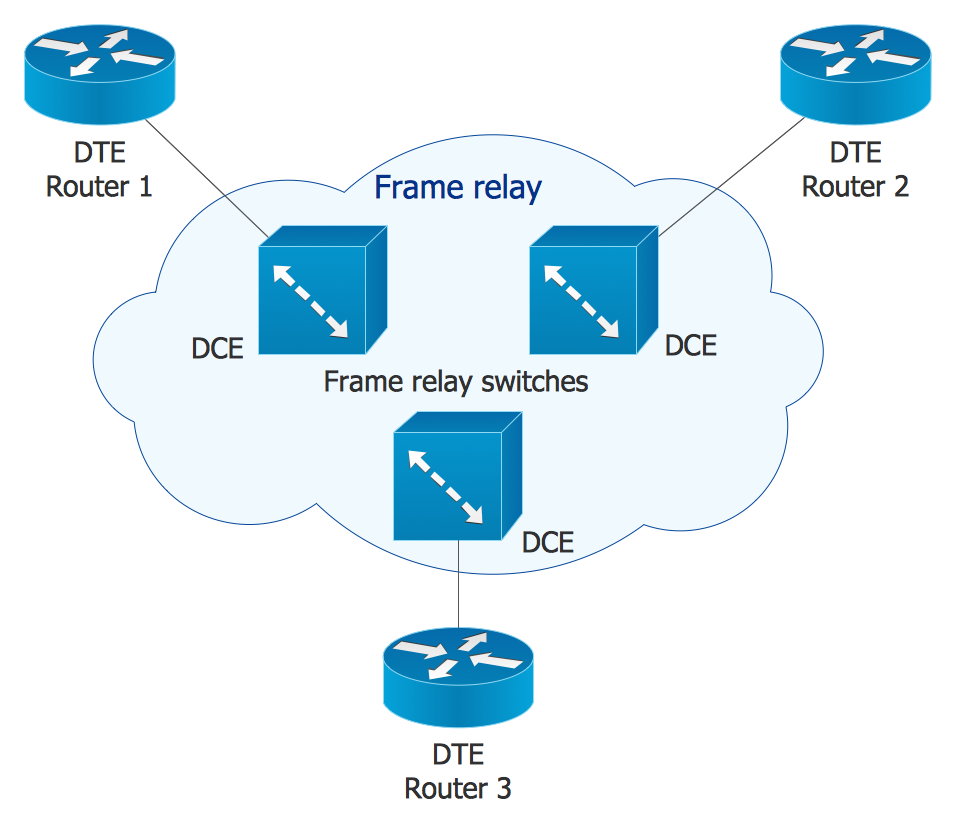
"When multiple routers are used in interconnected networks, the routers exchange information about destination addresses using a dynamic routing protocol. Each router builds up a table listing the preferred routes between any two systems on the interconnected networks. A router has interfaces for different physical types of network connections, (such as copper cables, fiber optic, or wireless transmission). It also contains firmware for different networking Communications protocol standards. Each network interface uses this specialized computer software to enable data packets to be forwarded from one protocol transmission system to another.
Routers may also be used to connect two or more logical groups of computer devices known as subnets, each with a different sub-network address. The subnets addresses recorded in the router do not necessarily map directly to the physical interface connections." [Router (computing). Wikipedia]
The symbols example "Cisco routers - Vector stencils library" was created using the ConceptDraw PRO diagramming and vector drawing software extended with the Cisco Network Diagrams solution from the Computer and Networks area of ConceptDraw Solution Park.
www.conceptdraw.com/ solution-park/ computer-networks-cisco
Router

Router, subdued

Router with silicon switch

Wavelength router

NetFlow router

uBR 910

Broadband router

Gigabit switch ATM tag router

ATM tag switch router

ATM router

NetFlow router

Cisco 7505

Cisco 7507

Cisco 7500 ARS (7513)
-cisco-routers---vector-stencils-library.png--diagram-flowchart-example.png)
Voice enabled router

TDM router

IP telephony router

IAD router

Content service router

Cisco storage router

Router with firewall

Wireless router

ASR 1000 series

ATM 3800

AXP

Cable modem

Ground terminal

Cisco Network Objects in ConceptDraw DIAGRAM
Design Element: Network Layout for Network Diagrams
.png)
Design Element: Rack Diagram for Network Diagrams
.png)
Cisco Network Icons
- Cable Network . Computer and Network Examples | Network ...
- Design elements - Cable TV (CATV) | Cable TV - Vector stencils ...
- ConceptDraw PRO Network Diagram Tool | Design elements ...
- Cable TV - Vector stencils library | Design elements - Cable TV ...
- Network layout floorplan - Vector stencils library | Cable TV - Vector ...
- Cable TV - Vector stencils library | Network wiring cable . Computer ...
- Cable Network Symbols
- Star Network Topology | Cable TV - Vector stencils library | Cable TV ...
- Network Layout Floor Plans | Network layout floorplan - Vector ...
- Cable TV - Vector stencils library
- Network Topologies | Design elements - Cable TV (CATV) | Network ...
- Design elements - Cable TV (CATV) | Television networks ...
- Tree Network Topology Diagram | Design elements - Cable TV ...
- Fiber Optic Cable Network Diagram Software
- Regional cable head-end diagram | Cable TV - Vector stencils ...
- Cisco Network Topology | Network Diagramming Software for ...
- Network Cable Diagram For Wires
- ConceptDraw PRO Network Diagram Tool | Electrical Drawing ...
- Network Cable Layout Plan
- Design elements - Cable TV (CATV)