Point to Point Network Topology

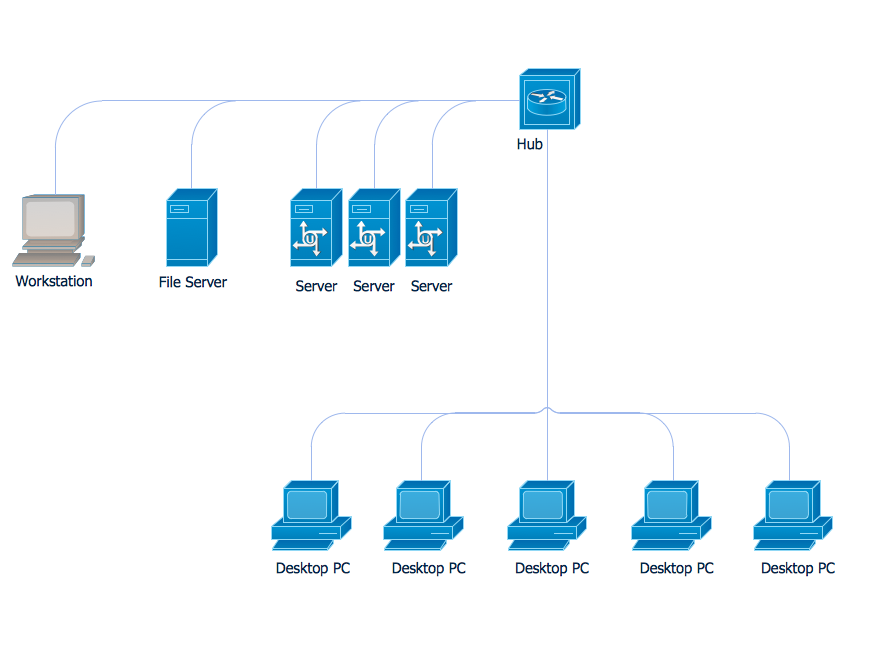
Star Network Topology


Network Topologies

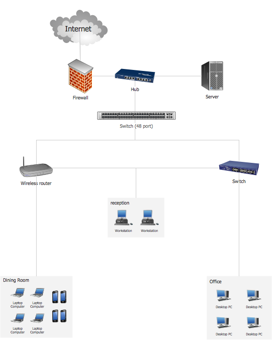
Hotel Network Topology Diagram

"Network topology is the arrangement of the various elements (links, nodes, etc.) of a computer network. Essentially, it is the topological structure of a network, and may be depicted physically or logically. Physical topology refers to the placement of the network's various components, including device location and cable installation, while logical topology shows how data flows within a network, regardless of its physical design. Distances between nodes, physical interconnections, transmission rates, and/ or signal types may differ between two networks, yet their topologies may be identical. The study of network topology recognizes eight basic topologies: Point-to-point, Bus, Star, Ring or circular, Mesh, Tree, Hybrid, Daisy chain." [Network topology. Wikipedia]
The computer network topologies diagram example was created using the ConceptDraw PRO diagramming and vector drawing software extended with the Computer and Networks solution from the Computer and Networks area of ConceptDraw Solution Park.
The computer network topologies diagram example was created using the ConceptDraw PRO diagramming and vector drawing software extended with the Computer and Networks solution from the Computer and Networks area of ConceptDraw Solution Park.
Network topologies

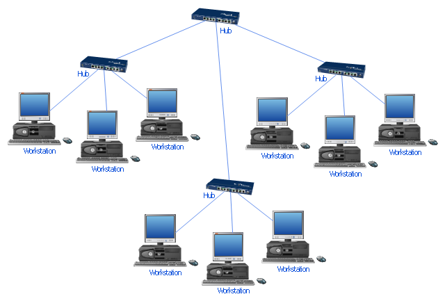
Tree Network Topology Diagram

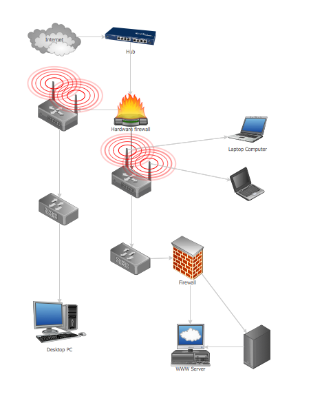
Wireless Network Topology

The vector stencils library "Cisco network topology" contains 89 symbols of Cisco network devices and design elements for drawing computer network topology diagrams.
"There are two basic categories of network topologies:
(1) Physical topologies,
(2) Logical topologies.
The shape of the cabling layout used to link devices is called the physical topology of the network. This refers to the layout of cabling, the locations of nodes, and the interconnections between the nodes and the cabling. The physical topology of a network is determined by the capabilities of the network access devices and media, the level of control or fault tolerance desired, and the cost associated with cabling or telecommunications circuits.
The logical topology in contrast, is the way that the signals act on the network media, or the way that the data passes through the network from one device to the next without regard to the physical interconnection of the devices." [Network topology. Wikipedia]
The symbols example "Cisco network topology - Vector stencils library" was created using the ConceptDraw PRO diagramming and vector drawing software extended with the Cisco Network Diagrams solution from the Computer and Networks area of ConceptDraw Solution Park.
www.conceptdraw.com/ solution-park/ computer-networks-cisco
Router

Broadband router

Router firewall

Wireless router

Workgroup switch

ATM switch

ISDN switch

Multilayer switch

Protocol translator

Communications server

Transpath

Bridge

Terminal server

Route switch processor

Content engine (cache director)
-cisco-network-topology---vector-stencils-library.png--diagram-flowchart-example.png)
Management engine (ME 1100)
-cisco-network-topology---vector-stencils-library.png--diagram-flowchart-example.png)
Switch processor

ITP

Voice gateway

BBSM

ATA

SIP Proxy server

NetRanger

Cisco 1000

IP

System controller

ACE

Directory server

ADM

Cisco Unity Express

Unity server

Cisco security

CallManager

DSLAM

H.323

CDM (Content Distribution Manager)
-cisco-network-topology---vector-stencils-library.png--diagram-flowchart-example.png)
ICM

Access point

Wireless bridge

Wireless connectivity

Guard

Mobile access router

Carrier Routing System (CRS)
-cisco-network-topology---vector-stencils-library.png--diagram-flowchart-example.png)
Vault

Workstation

PC

Macintosh

Cloud, gold

Cloud, white

Cloud, standard color

Cisco security management

PBX

DPT

Government building

Headquarters, blue

Router in building

Man

Woman

Workgroup switch, subdued

Router, subdued

File server

Firewall, horizontal

Firewall, vertical

Firewall, vertical, subdued

Lock

Key

Lock and key

Car

Truck

File cabinet

Breakout box

Breakout box, blue

Host

Relational database

Modem

BBS (Bulletin Board System)
-cisco-network-topology---vector-stencils-library.png--diagram-flowchart-example.png)
Satellite

Satellite dish

UPS

RPS

MAU

PAD

PAD X.28

Diskette

Contact center

Page icon
Antenna

Antenna, blue

Radio tower

Virtual networks. Computer and Network Examples


The vector stencils library "Cisco network topology" contains 89 symbols of Cisco network devices and design elements for drawing computer network topology diagrams.
"There are two basic categories of network topologies:
(1) Physical topologies,
(2) Logical topologies.
The shape of the cabling layout used to link devices is called the physical topology of the network. This refers to the layout of cabling, the locations of nodes, and the interconnections between the nodes and the cabling. The physical topology of a network is determined by the capabilities of the network access devices and media, the level of control or fault tolerance desired, and the cost associated with cabling or telecommunications circuits.
The logical topology in contrast, is the way that the signals act on the network media, or the way that the data passes through the network from one device to the next without regard to the physical interconnection of the devices." [Network topology. Wikipedia]
The symbols example "Cisco network topology - Vector stencils library" was created using the ConceptDraw PRO diagramming and vector drawing software extended with the Cisco Network Diagrams solution from the Computer and Networks area of ConceptDraw Solution Park.
www.conceptdraw.com/ solution-park/ computer-networks-cisco
"There are two basic categories of network topologies:
(1) Physical topologies,
(2) Logical topologies.
The shape of the cabling layout used to link devices is called the physical topology of the network. This refers to the layout of cabling, the locations of nodes, and the interconnections between the nodes and the cabling. The physical topology of a network is determined by the capabilities of the network access devices and media, the level of control or fault tolerance desired, and the cost associated with cabling or telecommunications circuits.
The logical topology in contrast, is the way that the signals act on the network media, or the way that the data passes through the network from one device to the next without regard to the physical interconnection of the devices." [Network topology. Wikipedia]
The symbols example "Cisco network topology - Vector stencils library" was created using the ConceptDraw PRO diagramming and vector drawing software extended with the Cisco Network Diagrams solution from the Computer and Networks area of ConceptDraw Solution Park.
www.conceptdraw.com/ solution-park/ computer-networks-cisco
Router
Broadband router
Router firewall
Wireless router
Workgroup switch
ATM switch
ISDN switch
Multilayer switch
Protocol translator
Communications server
Transpath
Bridge
Terminal server
Route switch processor
Content engine (cache director)
Management engine (ME 1100)
Switch processor
ITP
Voice gateway
BBSM
ATA
SIP Proxy server
NetRanger
Cisco 1000
IP
System controller
ACE
Directory server
ADM
Cisco Unity Express
Unity server
Cisco security
CallManager
DSLAM
H.323
CDM (Content Distribution Manager)
ICM
Access point
Wireless bridge
Wireless connectivity
Guard
Mobile access router
Carrier Routing System (CRS)
Vault
Workstation
PC
Macintosh
Cloud, gold
Cloud, white
Cloud, standard color
Cisco security management
PBX
DPT
Government building
Headquarters, blue
Router in building
Man
Woman
Workgroup switch, subdued
Router, subdued
File server
Firewall, horizontal
Firewall, vertical
Firewall, vertical, subdued
Lock
Key
Lock and key
Car
Truck
File cabinet
Breakout box
Breakout box, blue
Host
Relational database
Modem
BBS (Bulletin Board System)
Satellite
Satellite dish
UPS
RPS
MAU
PAD
PAD X.28
Diskette
Contact center
Page icon
Antenna
Antenna, blue
Radio tower
Network Glossary Definition

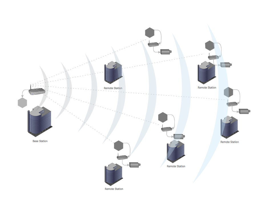
Point-to-multipoint (P2MP) Network. Computer and Network Examples
Cisco Network Topology. Cisco icons, shapes, stencils and symbols

Bus Network Topology

Communication Network Topology
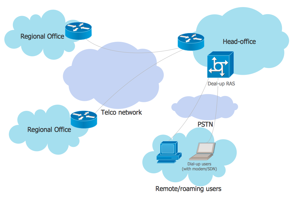
Digital Communications Network. Computer and Network Examples

"Star networks are one of the most common computer network topologies. In its simplest form, a star network consists of one central switch, hub or computer, which act as a conduit to transmit messages. This consists of a central node, to which all other nodes are connected; this central node provides a common connection point for all nodes through a hub. In star topology, every node (computer workstation or any other peripheral) is connected to a central node called a hub or switch. The switch is the server and the peripherals are the clients. Thus, the hub and leaf nodes, and the transmission lines between them, form a graph with the topology of a star." [Star network. Wikipedia]
The computer network diagram example "10Base-T star topology" was created using the ConceptDraw PRO diagramming and vector drawing software extended with the Computer and Networks solution from the Computer and Networks area of ConceptDraw Solution Park.
The computer network diagram example "10Base-T star topology" was created using the ConceptDraw PRO diagramming and vector drawing software extended with the Computer and Networks solution from the Computer and Networks area of ConceptDraw Solution Park.
Star topology
Hotel Network Topology
Guesthouse Network
EPN Frame-Relay and Dial-up Network. Computer and Network Examples
- Star Network Topology | Hotel Network Topology Diagram | Network ...
- Network Topology | Basic Network Diagram | Point to Point Network ...
- Network topologies diagram | Network Topology | Cisco Network ...
- Tree Network Topology Diagram | Network Topologies | Star ...
- Hybrid Network Topology | Star Network Topology | Network ...
- Interactive Voice Response Network Diagram | Cisco Network ...
- Diagram Physical Topologies | Hotel Network Topology Diagram ...
- Design Elements - Trango, Tranzeo | Network Gateway Router ...
- Network Topology | How to Draw a Computer Network Diagrams ...
- Using Both Wired and Wireless Connections | Wireless access point ...
- Network Topology | Basic Network Diagram | Daisy Chain Network ...
- Communication Network Topology
- Cisco Network Topology | Network Diagram Software Topology ...
- Star Network Topology | 10Base-T star topology - Network diagram ...
- Computer Networking Tools List | Design elements - Network layout ...
- Cisco Network Topology | Wireless mesh network diagram | Cisco ...
- 10Base-T star network topology diagram | Network Diagram ...
- Network Topology | Hotel Network Topology Diagram. Hotel ...
- Network Diagram Examples | Bus network topology diagram | Basic ...
- Telecommunication Network Diagrams | Computer and Networks ...