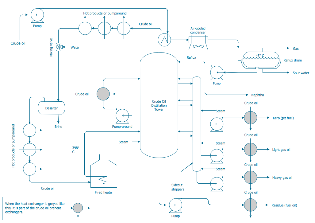
Process and Instrumentation Diagram
Piping and Instrumentation Diagram Software

 Chemical and Process Engineering
This chemical engineering solution extends ConceptDraw DIAGRAM.9.5 (or later) with process flow diagram symbols, samples, process diagrams templates and libraries of design elements for creating process and instrumentation diagrams, block flow diagrams (BFD
Flow chart Example. Warehouse Flowchart


Mechanical Drawing Symbols

Process Flowchart


 Plumbing and Piping Plans
Plumbing and Piping Plans solution extends ConceptDraw DIAGRAM.2.2 software with samples, templates and libraries of pipes, plumbing, and valves design elements for developing of water and plumbing systems, and for drawing Plumbing plan, Piping plan, PVC Pipe plan, PVC Pipe furniture plan, Plumbing layout plan, Plumbing floor plan, Half pipe plans, Pipe bender plans.
Flow Diagram Software

 Landscape & Garden
The Landscape and Gardens solution for ConceptDraw DIAGRAM is the ideal drawing tool when creating landscape plans. Any gardener wondering how to design a garden can find the most effective way with Landscape and Gardens solution.
Program Evaluation and Review Technique (PERT) with ConceptDraw DIAGRAM

- Piping And Instrumentation Diagram Book Pdf
- Piping And Instrumentation Diagram Symbols Pdf
- Plumbing and Piping Plans | Pipe Fittings Graphics Images Pdf
- Plumbing and Piping Plans | Piping and instrumentation diagram ...
- Plant Layout Plans | Erd Pipes Industry Pdf
- Plant Layout Pdf
- How to Create a Residential Plumbing Plan | Plumbing and Piping ...
- Building Drawing Design Element: Piping Plan | Plumbing and ...
- Plant Layout Drawings Pdf