Diagram Physical Topologies
Physical network. Computer and Network Examples

Network Diagram Software Physical Network Diagram

"Logical topology, or signal topology, is the arrangement of devices on a computer network and how they communicate with one another. How devices are connected to the network through the actual cables that transmit data, or the physical structure of the network, is called the physical topology. Physical topology defines how the systems are physically connected. It represents the physical layout of the devices on the network. The logical topology defines how the systems communicate across the physical topologies.
Logical topologies are bound to network protocols and describe how data is moved across the network. ...
EXAMPLE : twisted pair Ethernet is a logical bus topology in a physical star topology layout. while IBM's token ring is a logical ring topology, it is physically set up in star topology." [Logical topology. Wikipedia]
This Cisco logical computer network diagram example was created using the ConceptDraw PRO diagramming and vector drawing software extended with the Cisco Network Diagrams solution from the Computer and Networks area of ConceptDraw Solution Park.
Logical network topology diagram

Wide area network (WAN) topology. Computer and Network Examples

"Physical topology refers to the placement of the network's various components, including device location and cable installation...
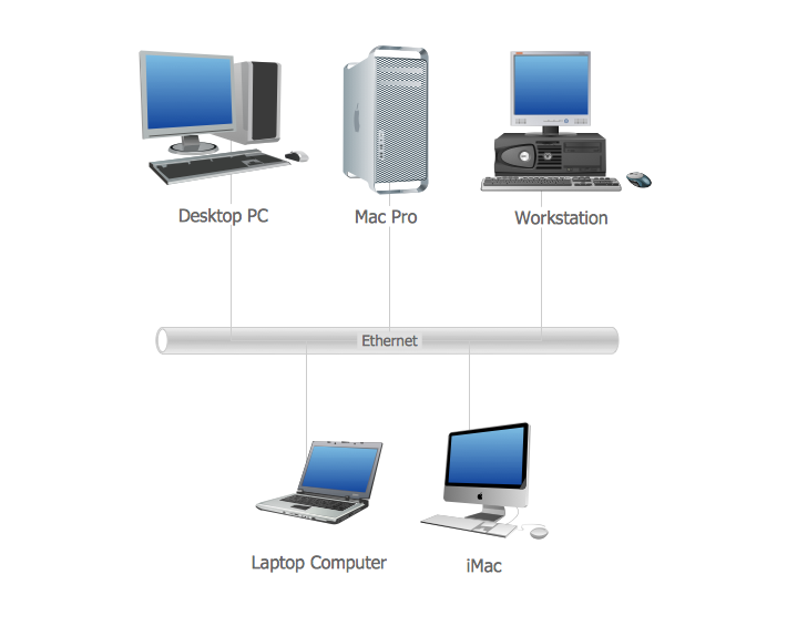
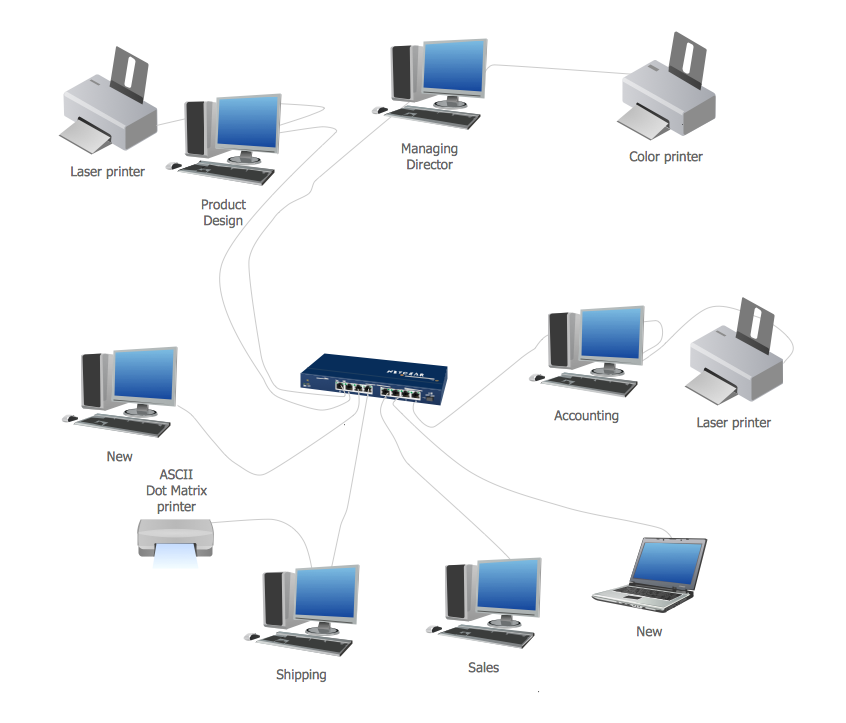
The shape of the cabling layout used to link devices is called the physical topology of the network. This refers to the layout of cabling, the locations of nodes, and the interconnections between the nodes and the cabling. The physical topology of a network is determined by the capabilities of the network access devices and media, the level of control or fault tolerance desired, and the cost associated with cabling or telecommunications circuits." [Network topology. Wikipedia]
This physical LAN diagram example was created using the ConceptDraw PRO diagramming and vector drawing software extended with the Computer and Networks solution from the Computer and Networks area of ConceptDraw Solution Park.
LAN physical topology

Used Solutions
Local area network (LAN). Computer and Network Examples
 diagram")
Virtual private networks (VPN). Computer and Network Examples

 Computer Network Diagrams
Computer Network Diagrams solution extends ConceptDraw DIAGRAM software with samples, templates and libraries of vector icons and objects of computer network devices and network components to help you create professional-looking Computer Network Diagrams, to plan simple home networks and complex computer network configurations for large buildings, to represent their schemes in a comprehensible graphical view, to document computer networks configurations, to depict the interactions between network's components, the used protocols and topologies, to represent physical and logical network structures, to compare visually different topologies and to depict their combinations, to represent in details the network structure with help of schemes, to study and analyze the network configurations, to communicate effectively to engineers, stakeholders and end-users, to track network working and troubleshoot, if necessary.
Wireless Network Topology

- Physical Topology Examples Diagram
- Diagram Physical Topologies | Physical LAN topology diagram ...
- Logical network topology diagram | Physical Topology Diagrams ...
- Physical And Logical Network Layout
- Wide area network (WAN) topology . Computer and Network ...
- Logical Network Diagram Vs Physical Network Diagram
- Physical LAN topology diagram | Logical network topology diagram ...
- Network Diagram Examples | Network Diagram Software Physical ...
- Physical Network Diagram Vs Logical
- Network Diagram Examples | Cisco Network Templates | Network ...