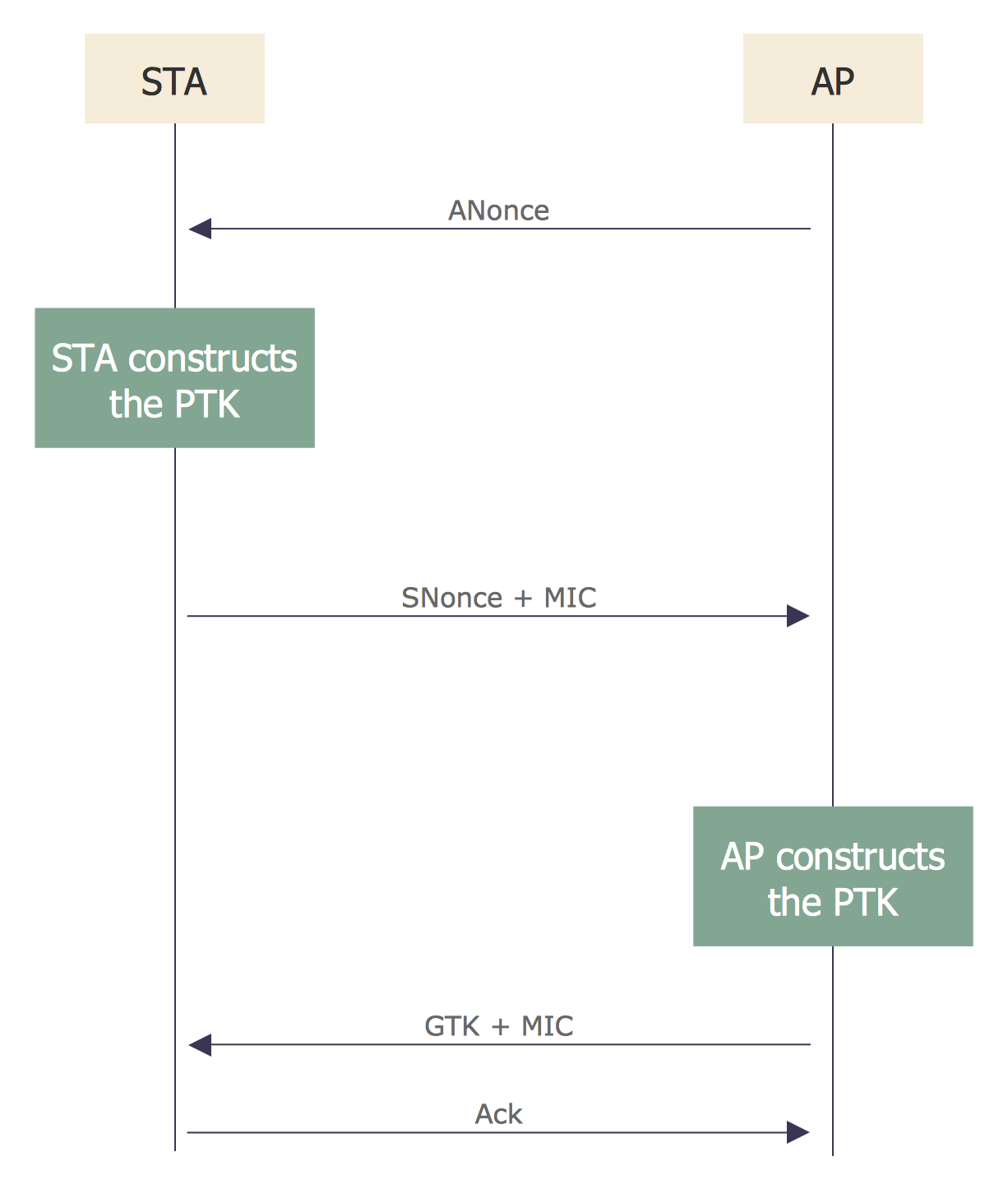
Sequence Diagram for Cloud Computing
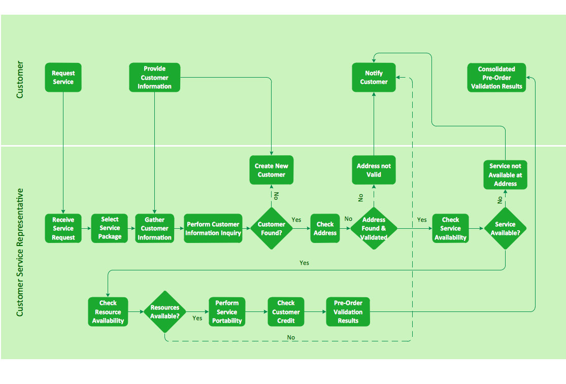
Cross-functional flowchart landscape, U.S. units
Site Plan

Relative Value Chart Software

Mechanical Drawing Symbols

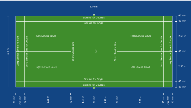
This sport field plan sample depicts the badminton court arena.
"The court is rectangular and divided into halves by a net. Courts are usually marked for both singles and doubles play, although badminton rules permit a court to be marked for singles only. The doubles court is wider than the singles court, but both are of same length. The exception, which often causes confusion to newer players, is that the doubles court has a shorter serve-length dimension.
The full width of the court is 6.1 metres (20 ft), and in singles this width is reduced to 5.18 metres (17 ft). The full length of the court is 13.4 metres (44 ft). The service courts are marked by a centre line dividing the width of the court, by a short service line at a distance of 1.98 metres (6 ft 6 inch) from the net, and by the outer side and back boundaries. In doubles, the service court is also marked by a long service line, which is 0.76 metres (2 ft 6 inch) from the back boundary.
The net is 1.55 metres (5 ft 1 inch) high at the edges and 1.524 metres (5 ft) high in the centre. The net posts are placed over the doubles sidelines, even when singles is played." [Badminton. Wikipedia]
The sport field plan example "Badminton court" was created using the ConceptDraw PRO diagramming and vector drawing software extended with the Sport Field Plans solution from the Building Plans area of ConceptDraw Solution Park.
Sport field plan
Sales Steps

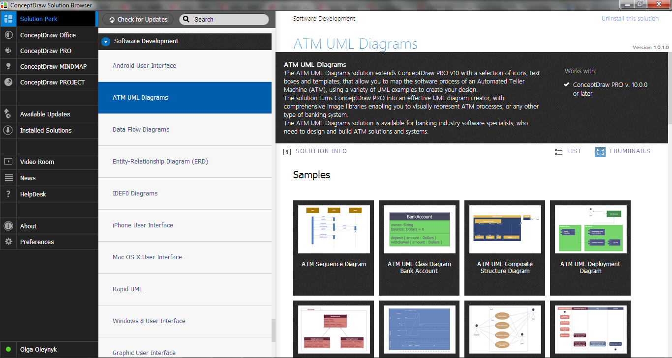
ATM Solutions
ConceptDraw Arrows10 Technology

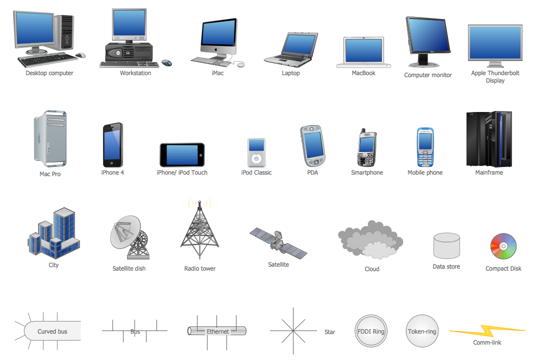
Network Icon
Sales Process

 Floor Plans
Construction, repair and remodeling of the home, flat, office, or any other building or premise begins with the development of detailed building plan and floor plans. Correct and quick visualization of the building ideas is important for further construction of any building.
Network Security Architecture Diagram

HelpDesk
How to Create a Plant Layout Design

Business Processes

- Mechanical Drawing Symbols | Fluid power equipment - Vector ...
- Mechanical Drawing Symbols | Design elements - Fluid power ...
- IVR phones - Vector stencils library | How to Create an Interactive ...
- Badminton court | Sport fields and recreation - Vector stencils library ...
- IVR business - Vector stencils library | Eisenhower box | Business ...
- Basic Flowchart Symbols and Meaning | Cloud round icons - Vector ...
- Cloud round icons - Vector stencils library | Cloud round icons ...
- Mechanical Drawing Symbols | Hydraulic pumps and motors ...
- Vector Diagram For Pneumatics
- Sales department - Vector stencils library | HR department - Vector ...
- Mechanical Drawing Symbols | Cloud clipart - Vector stencils library ...
- Business Process Diagrams | Business Package for Management ...
- Cloud round icons - Vector stencils library | Example of DFD for ...
- Cloud round icons - Vector stencils library | Education pictograms ...
- Design elements - Vessels | Mechanical Drawing Symbols | Vessels ...
- Road transport - Vector stencils library | UML for Software Engineers ...
- Process Flowchart | AWS Security, Identity and Compliance - Vector ...
- Sales workflow - Vector stencils library | Rapid UML | Business ...
- Education pictograms - Vector stencils library | Process Flowchart ...
- Process Flowchart | Business Process Diagrams | Workflow ...