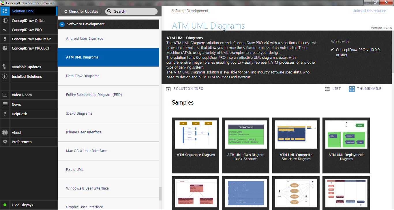
Example 1. ATM Solutions in ConceptDraw STORE
ATM Solutions are helpful for easy drawing ATM UML and Bank UML diagrams. Large collection of predesigned samples and variety of libraries with numerous vector objects are included in ATM UML Diagrams Solution for ConceptDraw DIAGRAM

Example 2. OPC Runtime Refinement View
All 14 libraries and full collection of professionally developed samples are available from ConceptDraw STORE which permit to click any preview to open it for editing in ConceptDraw DIAGRAM software.

Example 3. ATM UML Deployment Diagram
The samples you see on this page were created in ConceptDraw DIAGRAM using the tools of ATM UML Diagrams Solution. These ATM UML diagrams are available for viewing and editing from ConceptDraw STORE. An experienced user spent 15-20 minutes creating each of them.
Use the ATM Solutions, particularly ATM UML Diagrams Solution for ConceptDraw DIAGRAM software to create your own professional looking ATM UML Diagrams without efforts.
All source documents are vector graphic documents. They are available for reviewing, modifying, or converting to a variety of formats (PDF file, MS PowerPoint, MS Visio, and many other graphic formats) from the ConceptDraw STORE. The ATM UML Diagrams Solution is available for all ConceptDraw DIAGRAM users.
SIX RELATED HOW TO's:
ConceptDraw DIAGRAM diagramming software provides vector shapes and connector tools for quick and easy drawing diagrams for business, technology, science and education.
Use ConceptDraw DIAGRAM enhanced with solutions from ConceptDraw Solution Park to create diagrams to present and explain structures, process flows, logical relationships, networks, design schemes and other visually organized information and knowledge.
Picture: Cross-Functional Flowchart - The easiest way to draw crossfunctional
This method of problem analysis is widely used in IT, manufacture industries and chemical engineering. If you want to take a fresh look on your problem, you can draw a fishbone diagram with ConceptDraw DIAGRAM software, which supports both MAC OS and Windows. You can see and download fishbone diagram samples and templates in ConceptDraw Solution Park.
This Fishbone (Ishikawa) diagram can be applied as template for performing the cause and effect analysis of a service industry problems. It can help to determine factors causing problems. Causes in this diagram are categorized according to the 4S’s principle that means Surroundings, Suppliers, Systems and Skills. Grouping causes allows to reveal main interactions between different events. This diagram was made using ConceptDraw Fishbone diagrams solution. It can help to reveal the causes effected a complicated issue. Of course it can be used together with other methods of approaching to the problem solving.
Picture: Draw Fishbone Diagram on MAC Software
Related Solution:
New Smart connectors in ConceptDraw DIAGRAM now have an auto-routing feature. This means that connectors always find the optimal route between objects and automatically recalculate that path when moving these objects.
You don't have to think about your connectors, they think for you.
Picture: ConceptDraw Arrows10 Technology
Network Security Architecture Diagram visually reflects the network's structure and construction, and all actions undertaken for ensuring the network security which can be executed with help of software resources and hardware devices. You dream to find powerful software for easy designing Network Security Architecture Diagram? We recommend to use ConceptDraw DIAGRAM extended with Network Security Diagrams Solution from the Computer and Networks Area of ConceptDraw Solution Park.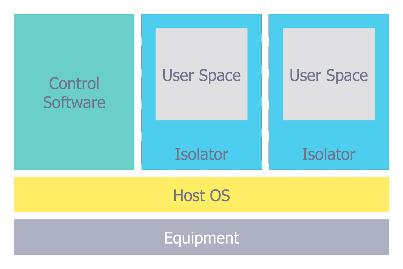
Picture: Network Security Architecture Diagram
Related Solution:
Microsoft Azure is widely used cloud platform which was created by Microsoft and now is managed by Microsoft datacenters in 19 regions of the world, and has a wide set of benefits and features.
ConceptDraw DIAGRAM diagramming and vector drawing software extended with Azure Architecture Solution from the Computer and Networks area of ConceptDraw Solution Park is the best for designing various pictorial infographics, illustrations and materials showing the possibilities and work of Microsoft Azure Cloud System and Azure services.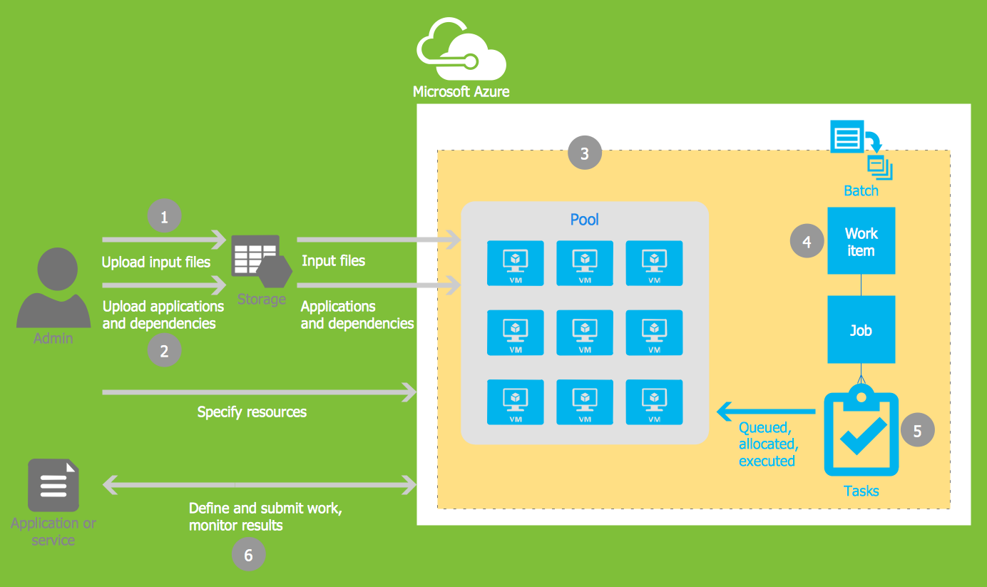
Picture: Microsoft Azure
Related Solution:
Computer and Networks solution provides examples, templates and vector stencils library with symbols of local area network (LAN) and wireless LAN (WLAN) equipment.
This example of computer network topology diagram shows home WLAN equipment and their connection to the Internet.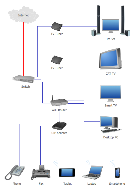
Picture: Network Topology Graphical Examples
Related Solution:

