Entity Relationship Diagram Examples


Entity Relationship Diagram Symbols

Modelling Concepts for Business Engineering - EPC

Data Modeling with Entity Relationship Diagram

UML Class Diagram Generalization Example UML Diagrams

Business Process Mapping — How to Map a Work Process

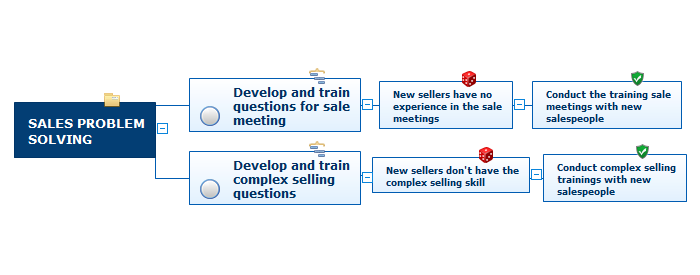
Risk Diagram (Process Decision Program Chart)
 Entity-Relationship Diagram (ERD)
An Entity-Relationship Diagram (ERD) is a visual presentation of entities and relationships. That type of diagrams is often used in the semi-structured or unstructured data in databases and information systems. At first glance ERD is similar to a flowch
Data structure diagram with ConceptDraw DIAGRAM

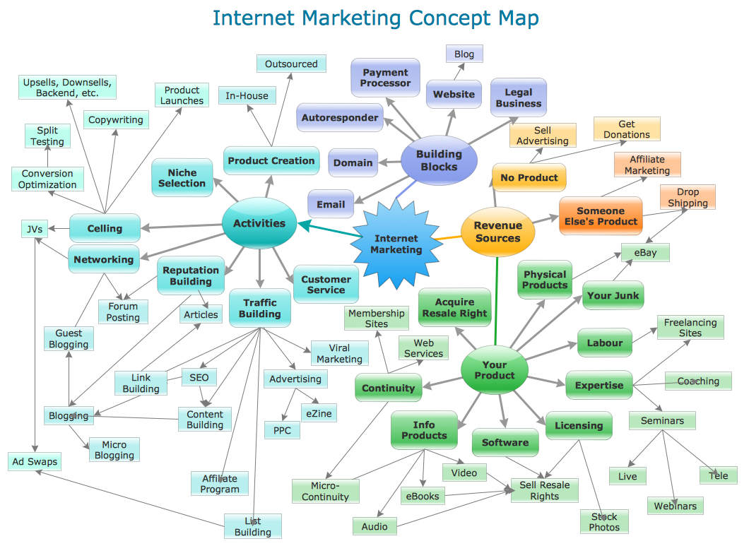
Concept Maps
- Mind Map Interrelationship Digraph
- Relations diagram - Health care | Relations diagram - Template ...
- Interrelationship Digraph Example
- Mind Map Exchange | Entity- Relationship Diagram (ERD) | How to ...
- Relations diagram - Health care | Risk management - Concept map ...
- Cause And Effect Diagram Examples In Healthcare
- Entity Relationship Diagram Symbols | PROBLEM ANALYSIS ...
- Interrelationship Diagram Wikipedia
- IDEF1 standard | Relations diagram - Template | How to Create ...
- PM Easy | Mind Map Exchange | Mac Relationship Diagram Mindmap