 Computer Network Diagrams
Computer Network Diagrams solution extends ConceptDraw DIAGRAM software with samples, templates and libraries of vector icons and objects of computer network devices and network components to help you create professional-looking Computer Network Diagrams, to plan simple home networks and complex computer network configurations for large buildings, to represent their schemes in a comprehensible graphical view, to document computer networks configurations, to depict the interactions between network's components, the used protocols and topologies, to represent physical and logical network structures, to compare visually different topologies and to depict their combinations, to represent in details the network structure with help of schemes, to study and analyze the network configurations, to communicate effectively to engineers, stakeholders and end-users, to track network working and troubleshoot, if necessary.
UML Tool & UML Diagram Examples

Metropolitan area networks (MAN). Computer and Network Examples
. Computer and Network Examples")

Software Diagram Examples and Templates

Network Security Devices

Cisco Buildings. Cisco icons, shapes, stencils and symbols

 Network Layout Floor Plans
Network Layout Floor Plans solution extends ConceptDraw DIAGRAM software functionality with powerful tools for quick and efficient documentation the network equipment and displaying its location on the professionally designed Network Layout Floor Plans. Never before creation of Network Layout Floor Plans, Network Communication Plans, Network Topologies Plans and Network Topology Maps was not so easy, convenient and fast as with predesigned templates, samples, examples and comprehensive set of vector design elements included to the Network Layout Floor Plans solution. All listed types of plans will be a good support for the future correct cabling and installation of network equipment.
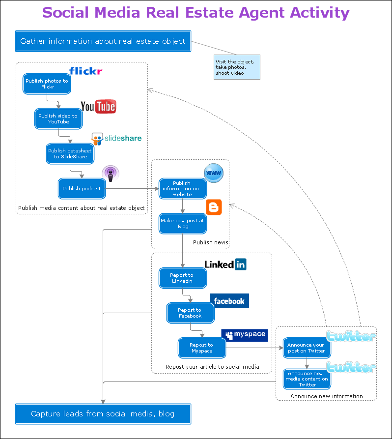
Organizing and Selecting Social Media Response Action
UML Notation

- Entity Relationship Diagram Examples | Network Diagram Examples ...
- Local area network ( LAN ). Computer and Network Examples ...
- Interior Design School Layout - Design Elements | Local area ...
- School Management System Diagram
- Activity Network Diagram Method | Project Timeline | Draw Network ...
- Local area network ( LAN ). Computer and Network Examples | Block ...
- Computer Network Diagrams | Local area network ( LAN ). Computer ...
- Personal area (PAN) networks . Computer and Network Examples ...
- Flow chart Example. Warehouse Flowchart | How to Create a ...
- Design elements - Internet symbols | Internet symbols - Vector ...