Hotel Network Topology Diagram


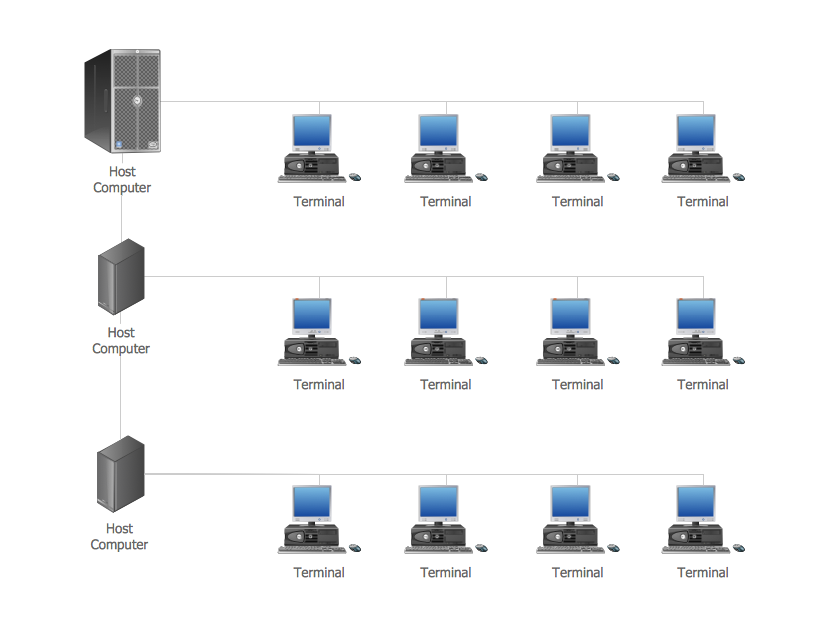
Star Network Topology

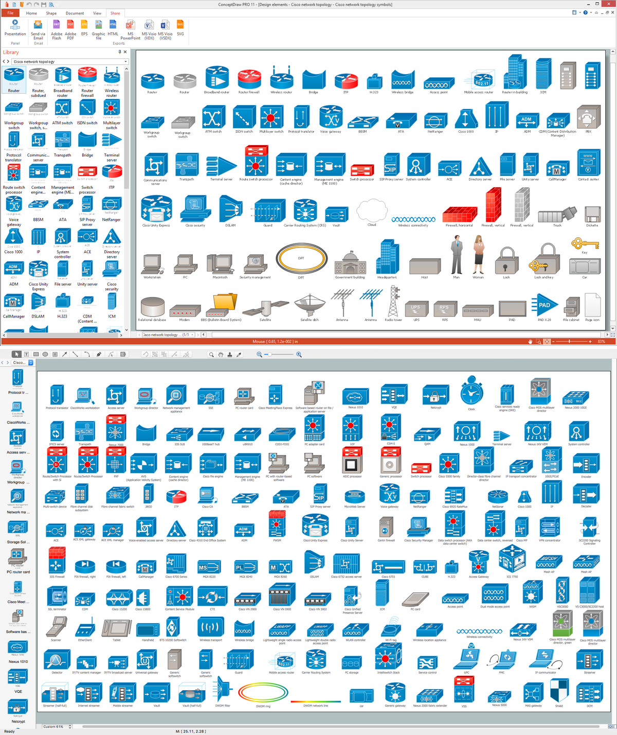
Cisco Network Topology. Cisco icons, shapes, stencils and symbols
"Network topology is the arrangement of the various elements (links, nodes, etc.) of a computer network. Essentially, it is the topological structure of a network, and may be depicted physically or logically. Physical topology refers to the placement of the network's various components, including device location and cable installation, while logical topology shows how data flows within a network, regardless of its physical design. Distances between nodes, physical interconnections, transmission rates, and/ or signal types may differ between two networks, yet their topologies may be identical. The study of network topology recognizes eight basic topologies: Point-to-point, Bus, Star, Ring or circular, Mesh, Tree, Hybrid, Daisy chain." [Network topology. Wikipedia]
The computer network topologies diagram example was created using the ConceptDraw PRO diagramming and vector drawing software extended with the Computer and Networks solution from the Computer and Networks area of ConceptDraw Solution Park.
The computer network topologies diagram example was created using the ConceptDraw PRO diagramming and vector drawing software extended with the Computer and Networks solution from the Computer and Networks area of ConceptDraw Solution Park.
Network topologies

The vector stencils library "Cisco network topology" contains 89 symbols of Cisco network devices and design elements for drawing computer network topology diagrams using the ConceptDraw PRO diagramming and vector drawing software.
"Network topology is an arrangement of the various elements (links, nodes, etc.) of a computer network. Essentially, it is the topological structure of a network, and may be depicted physically or logically. Physical topology refers to the placement of the network's various components, including device location and cable installation, while logical topology shows how data flows within a network, regardless of its physical design. Distances between nodes, physical interconnections, transmission rates, and/ or signal types may differ between two networks, yet their topologies may be identical.
A good example is a local area network (LAN): Any given node in the LAN has one or more physical links to other devices in the network; graphically mapping these links results in a geometric shape that can be used to describe the physical topology of the network. Conversely, mapping the data flow between the components determines the logical topology of the network." [Network topology. Wikipedia]
The example "Design elements - Cisco network topology" is included in the Cisco Network Diagrams solution from the Computer and Networks area of ConceptDraw Solution Park.
Cisco network topology symbols

Network Topologies

Computer Network. Computer and Network Examples

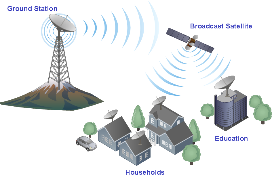
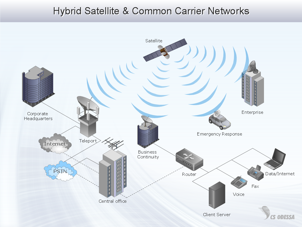
Telecommunication networks. Computer and Network Examples

Complete Network Topology

Wireless Networking for Mac
Virtual networks. Computer and Network Examples

Cisco Routers. Cisco icons, shapes, stencils and symbols

Network Diagramming with ConceptDraw DIAGRAM

Network Diagram Software Enterprise Private Network
- Network Topologies | Tree Network Topology Diagram | Fully ...
- Telecommunication Network Diagrams | Design elements ...
- Diagram Physical Topologies | Network Topologies | Logical ...
- Computer Network Bus Diagram
- Network Topology | Cisco Network Topology | Hotel Network ...
- Diagram Physical Topologies | Hotel Network Topology Diagram ...
- Point to Point Network Topology | Mesh Network Topology Diagram ...
- Network Topologies | Star Network Topology | Hotel Network ...
- Daisy Chain Network Topology | Hotel Network Topology Diagram ...
- Bus network topology diagram
- Network Topology | Network Diagram Examples | Cisco Network ...
- Network Hubs | Network Diagram Software Topology Network ...
- Daisy Chain Network Topology | Network Diagram Software LAN ...
- Star Network Topology | 10Base-T star topology - Network diagram ...
- Point to Point Network Topology | Star Network Topology | Hotel ...
- Hybrid Network Topology | Star Network Topology | 3D Network ...
- Basic computer network diagram | Network topologies diagram | In ...
- Network Topologies | Fully Connected Network Topology Diagram ...
- Computer network system design diagram | Design elements ...
- Daisy Chain Network Topology | Fully Connected Network Topology ...