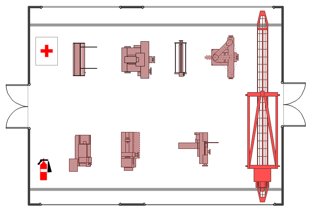
The example "Factory layout floor plan" shows manufacturing machines and equipment in the plant warehouse.
"A factory (previously manufactory) or manufacturing plant is an industrial site, usually consisting of buildings and machinery, or more commonly a complex having several buildings, where workers manufacture goods or operate machines processing one product into another.
Most modern factories have large warehouses or warehouse-like facilities that contain heavy equipment used for assembly line production. Large factories tend to be located with access to multiple modes of transportation, with some having rail, highway and water loading and unloading facilities." [Factory. Wikipedia]
The example "Factory layout floor plan" was created using the ConceptDraw PRO diagramming and vector drawing software extended with the Plant Layout Plans solution from the Building Plans area of ConceptDraw Solution Park.
Industrial equipment layout
How To use House Electrical Plan Software


How To Draw Building Plans


Emergency Plan

 Plant Layout Plans
This solution extends ConceptDraw PRO v.9.5 plant layout software (or later) with process plant layout and piping design samples, templates and libraries of vector stencils for drawing Plant Layout plans. Use it to develop plant layouts, power plant desig
 Building Plans Area
The Building Plans Area collects solutions for drawing the building and site plans.
The vector stencils library "Machines and equipment" contains 24 symbols of industrial machines and equipment.
Use the design elements library "Machines and equipment" for drawing plant interior design plans, manufacturing equipment layouts and factory floor plans using the ConceptDraw PRO diagramming and vector drawing software.
"Manufacturing is the production of goods for use or sale using labor and machines, tools, chemical and biological processing, or formulation. The term may refer to a range of human activity, from handicraft to high tech, but is most commonly applied to industrial production, in which raw materials are transformed into finished goods on a large scale.
Modern manufacturing includes all intermediate processes required for the production and integration of a product's components. Some industries, such as semiconductor and steel manufacturers use the term fabrication instead.
The manufacturing sector is closely connected with engineering and industrial design." [Manufacturing. Wikipedia]
The shapes library "Machines and equipment" is included in the Plant Layout Plans solution from the Building Plans area of ConceptDraw Solution Park.
Machines and equipment symbols

Network Diagram Software LAN Network Diagrams & Diagrams for LAN Physical Office Network Diagrams


Microsoft Azure

Plant Design

 Computer Network Diagrams
Computer Network Diagrams solution extends ConceptDraw PRO software with samples, templates and libraries of vector icons and objects of computer network devices and network components to help you create professional-looking Computer Network Diagrams, to plan simple home networks and complex computer network configurations for large buildings, to represent their schemes in a comprehensible graphical view, to document computer networks configurations, to depict the interactions between network's components, the used protocols and topologies, to represent physical and logical network structures, to compare visually different topologies and to depict their combinations, to represent in details the network structure with help of schemes, to study and analyze the network configurations, to communicate effectively to engineers, stakeholders and end-users, to track network working and troubleshoot, if necessary.
Network Engineering

- Plant Layout Plans | Factory layout floor plan | Restaurant Floor ...
- Factory layout floor plan | Cafe Floor Plan Design Software | Building ...
- Plant Layout Plans | Factory layout floor plan | Cafe and Restaurant ...
- Factory layout floor plan | Fire Exit Plan. Building Plan Examples ...
- Plant Layout Plans | Factory layout floor plan | Interior Design ...
- Plant Layout Plans | Factory layout floor plan | How to Create a Plant ...
- Factory layout floor plan | Plant Layout Plans | How To use House ...
- Factory layout floor plan | Plant Layout Plans | Design elements ...
- Factory layout floor plan | Building Drawing Software for Designing ...
- Plant Layout Plans | Factory layout floor plan | Restaurant Floor ...
- Factory layout floor plan | Buildings and green spaces - Vector ...
- Factory layout floor plan | Plant Layout Plans | Design elements ...
- Plant Layout Plans | Factory layout floor plan | How To Draw ...
- Factory layout floor plan
- Plant Layout Plans | Factory layout floor plan | Interior Design ...
- Plant Layout Plans | Factory layout floor plan | Building Drawing ...
- Factory layout floor plan | Plant Layout Plans | Restaurant Floor ...
- Factory layout floor plan | Plant Layout Plans | Video surveillance ...
- Factory layout floor plan | Interior Design Machines and Equipment ...
- Warehouse layout floor plan | Warehouse with conveyor system ...