UML Class Diagram Notation

UML Class Diagram. Design Elements

UML Composite Structure Diagram. Design Elements

UML Block Diagram

"In software engineering, a class diagram in the Unified Modeling Language (UML) is a type of static structure diagram that describes the structure of a system by showing the system's classes, their attributes, operations (or methods), and the relationships among objects." [Class diagram. Wikipedia]
This UML class diagram example was created using the ConceptDraw PRO diagramming and vector drawing software extended with the Rapid UML solution from the Software Development area of ConceptDraw Solution Park.
This UML class diagram example was created using the ConceptDraw PRO diagramming and vector drawing software extended with the Rapid UML solution from the Software Development area of ConceptDraw Solution Park.
UML class diagram
About UML

The vector stencils library "UML class diagrams" contains 38 symbols for the ConceptDraw PRO diagramming and vector drawing software.
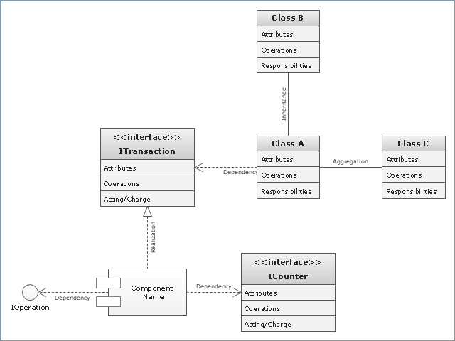
"... classes are represented with boxes which contain three parts:
(1) The top part contains the name of the class. It is printed in Bold, centered and the first letter capitalized.
(2) The middle part contains the attributes of the class. They are left aligned and the first letter is lower case.
(3) The bottom part gives the methods or operations the class can take or undertake. They are also left aligned and the first letter is lower case. ...
To indicate a classifier scope for a member, its name must be underlined. ...
An association can be named, and the ends of an association can be adorned with role names, ownership indicators, multiplicity, visibility, and other properties. ...
Aggregation ... is graphically represented as a hollow diamond shape on the containing class end of the tree with a single line that connects the contained class to the containing class.
... graphical representation of a composition relationship is a filled diamond shape on the containing class end of the tree of lines that connect contained class(es) to the containing class.
... graphical representation of a Generalization is a hollow triangle shape on the superclass end of the line (or tree of lines) that connects it to one or more subtypes.
... graphical representation of a Realization is a hollow triangle shape on the interface end of the dashed line (or tree of lines) that connects it to one or more implementers. A plain arrow head is used on the interface end of the dashed line that connects it to its users.
Multiplicity ... representation of an association is a line with an optional arrowhead indicating the role of the object(s) in the relationship, and an optional notation at each end indicating the multiplicity of instances of that entity (the number of objects that participate in the association).
Entity classes ... are drawn as circles with a short line attached to the bottom of the circle. Alternatively, they can be drawn as normal classes with the «entity» stereotype notation above the class name." [Class diagram. Wikipedia]
The example "Design elements - UML class diagrams" is included in the Rapid UML solution from the Software Development area of ConceptDraw Solution Park.
UML class diagram symbols

The vector stencils library "UML package diagrams" contains 21 symbols for the ConceptDraw PRO diagramming and vector drawing software.
"A package diagram in the Unified Modeling Language depicts the dependencies between the packages that make up a model. ...
Elements.
(1) Package: It is a general purpose mechanism for organizing model elements & diagrams into groups. It provides an encapsulated namespace within which all the names must be unique. It is used to group semantically related elements. It is a namespace as well as an element that can be contained in other package's namespaces.
(2) Class: It is a representation of objects, that reflects their structure and behavior within the system. It is a template from which actually running instances are created. Classes usually describe logical structure of system.
(3) Interface: It is a specification of behavior. Implementing classes of an interface class are required to support the behavior.
(4) Object: It is an instance of class. It is often used in analysis to represent numerous artifacts and items that exist.
(5) Table: It is a stereotyped class." [Package diagram. Wikipedia]
The example "Design elements - UML package diagrams" is included in the Rapid UML solution from the Software Development area of ConceptDraw Solution Park.
UML package diagram symbols

How to create a UML Diagram

"In software engineering, a class diagram in the Unified Modeling Language (UML) is a type of static structure diagram that describes the structure of a system by showing the system's classes, their attributes, operations (or methods), and the relationships among objects. ...
The class diagram is the main building block of object oriented modelling. It is used both for general conceptual modelling of the systematics of the application, and for detailed modelling translating the models into programming code. Class diagrams can also be used for data modeling. The classes in a class diagram represent both the main objects, interactions in the application and the classes to be programmed." [Class diagram. Wikipedia]
The template "UML class diagram" for the ConceptDraw PRO diagramming and vector drawing software is included in the Rapid UML solution from the Software Development area of ConceptDraw Solution Park.
www.conceptdraw.com/ solution-park/ software-uml
UML class diagram
The vector stencils library "Bank UML package diagram" contains 5 shapes for drawing UML package diagrams.
Use it for object-oriented modeling of your bank information system.
"A package diagram in the Unified Modeling Language depicts the dependencies between the packages that make up a model.
In addition to the standard UML Dependency relationship, there are two special types of dependencies defined between packages:
* package import,
* package merge.
Elements.
1. Package: a general purpose mechanism for organizing model elements & diagrams into groups. It provides an encapsulated namespace within which all the names must be unique. It is used to group semantically related elements. It is a namespace as well as an element that can be contained in other packages' namespaces.
2. Class: a representation of an object that reflects its structure and behavior within the system. It is a template from which running instances are created. Classes usually describe the logical structure of the system.
3. Interface: a specification of behavior. An implementation class must be written to support the behavior of an interface class.
4. Object: an instance of a class. It is often used in analysis to represent an artifact or other item.
5. Table: a stereotyped class." [Package diagram. Wikipedia]
This example of UML package diagram symbols for the ConceptDraw PRO diagramming and vector drawing software is included in the ATM UML Diagrams solution from the Software Development area of ConceptDraw Solution Park.
UML package diagram symbols

The vector stencils library "UML composite structure diagrams" contains 36 symbols for the ConceptDraw PRO diagramming and vector drawing software.
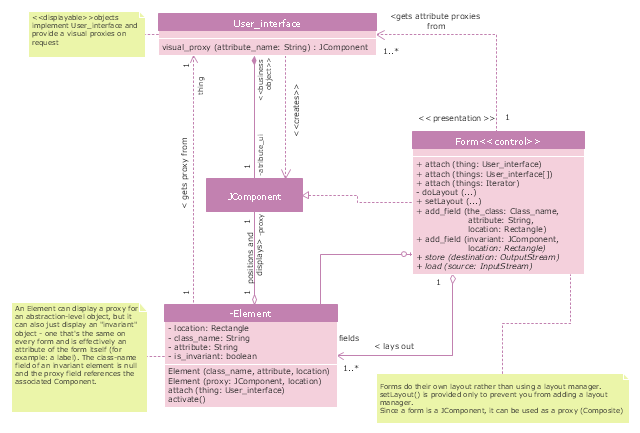
"The key composite structure entities identified in the UML 2.0 specification are structured classifiers, parts, ports, connectors, and collaborations.
(1) Part : A part represents a role played at runtime by one instance of a classifier or by a collection of instances. The part may only name the role, it may name an abstract superclass, or it may name a specific concrete class. The part can include a multiplicity factor, such as the [0..*] shown for Viewer in the diagram.
(2) Port : A port is an interaction point that can be used to connect structured classifiers with their parts and with the environment. Ports can optionally specify the services they provide and the services they require from other parts of the system. In the diagram, each of the small squares is a port. Each port has a type and is labelled with a name, such as "var", "indVar1", or "view" in the diagram. Ports may contain a multiplicity factor, for example.
Ports can either delegate received requests to internal parts, or they can deliver these directly to the behavior of the structured classifier that the port is contained within. Public ports that are visible in the environment are shown straddling the boundary, while protected ports that are not visible in the environment are shown inside the boundary. All the ports in the diagram are public, except for the view port along the right boundary of FibonacciSystem.
(3) Connector : A connector binds two or more entities together, allowing them to interact at runtime. The connector is shown as a line between some combination of parts, ports and structured classifiers. The diagram shows three connectors between ports, and one connector between a structured classifier and a part.
(4) Collaboration : A collaboration is generally more abstract than a structured classifier. It is shown as a dotted oval containing roles that instances can play in the collaboration.
(5) Structured classifier : A StructuredClassifier represents a class, often an abstract class, whose behavior can be completely or partially described through interactions between parts." [Composite structure diagram. Wikipedia]
The example "Design elements - UML composite structure diagrams" is included in the Rapid UML solution from the Software Development area of ConceptDraw Solution Park.
UML composite structure diagram symbols

Class Diagram Tool

Introductory Guide to Rapid UML Solution

 Android User Interface
The Android User Interface solution allows ConceptDraw PRO act as an Android UI design tool. Libraries and templates contain a variety of Android GUI elements to help users create images based on Android UI design.
- Class Interface
- UML class diagram - Template | Design elements - UML class ...
- Uml Class Diagram Interface
- Collaboration With Class Diagram With Interface In Uml For Simple
- What Is The Symbol And Notation For Class Diagram
- Design elements - Bank UML component diagram | Design ...
- UML Class Diagram Example for Transport System | Data Flow ...
- Class UML Diagram for Bank Account System | UML package ...
- Interface Uml Diagram
- UML Flowchart Symbols | UML Class Diagram Notation | Design ...
- UML class diagram
- UML Class Diagram Notation
- UML class diagram - Metadata information model | UML Diagram ...
- Design elements - Activities BPMN 1.2 | Windows Vista graphic user ...
- Uml Interface Diagram
- Diagramming Software for Design UML Package Diagrams | UML ...
- UML class diagram - Template
- Class Diagram Example Of Taxi
- UML Package Diagram. Design Elements | Diagramming Software ...
- UML Class Diagrams. Diagramming Software for Design UML ...