Network Glossary Definition


"Fault-tolerant computer systems are systems designed around the concepts of fault tolerance. In essence, they have to be able to keep working to a level of satisfaction in the presence of faults. ...
Most fault-tolerant computer systems are designed to be able to handle several possible failures, including hardware-related faults such as hard disk failures, input or output device failures, or other temporary or permanent failures; software bugs and errors; interface errors between the hardware and software, including driver failures; operator errors, such as erroneous keystrokes, bad command sequences, or installing unexpected software; and physical damage or other flaws introduced to the system from an outside source." [Fault-tolerant computer system. Wikipedia]
The computer network diagram example "Cisco LAN fault-tolerance system" was created using the ConceptDraw PRO diagramming and vector drawing software extended with the Cisco Network Diagrams solution from the Computer and Networks area of ConceptDraw Solution Park.
LAN fault-tolerance system

Used Solutions
Basic Flowchart Symbols and Meaning


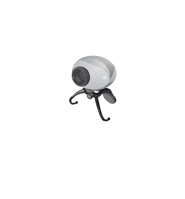
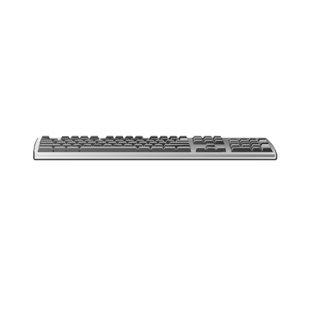
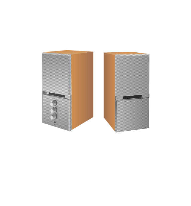
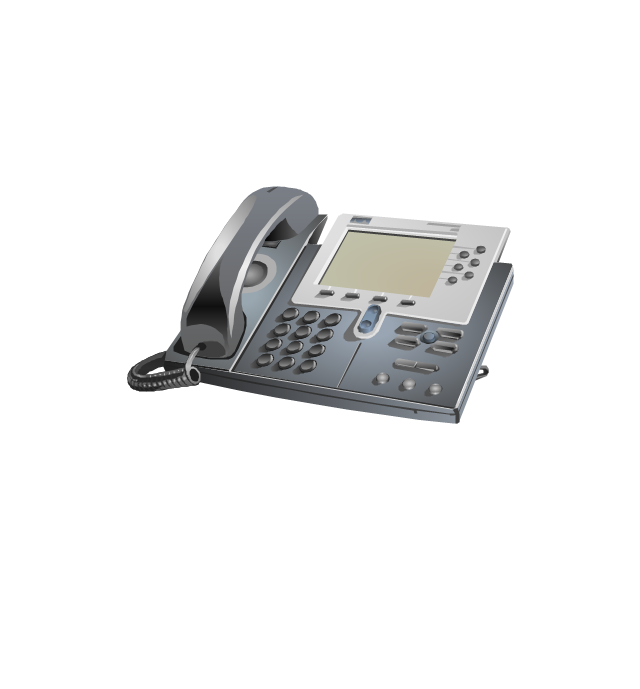
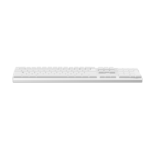
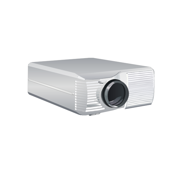
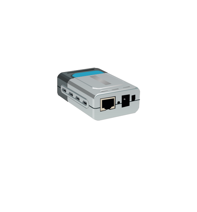
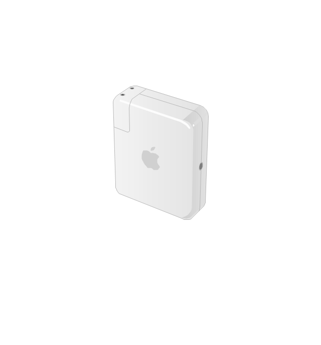
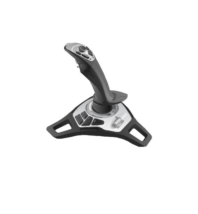
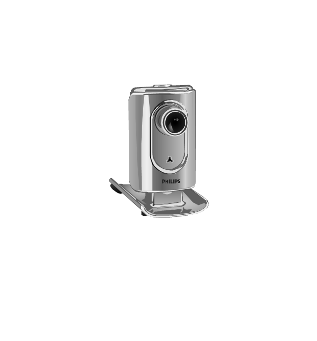
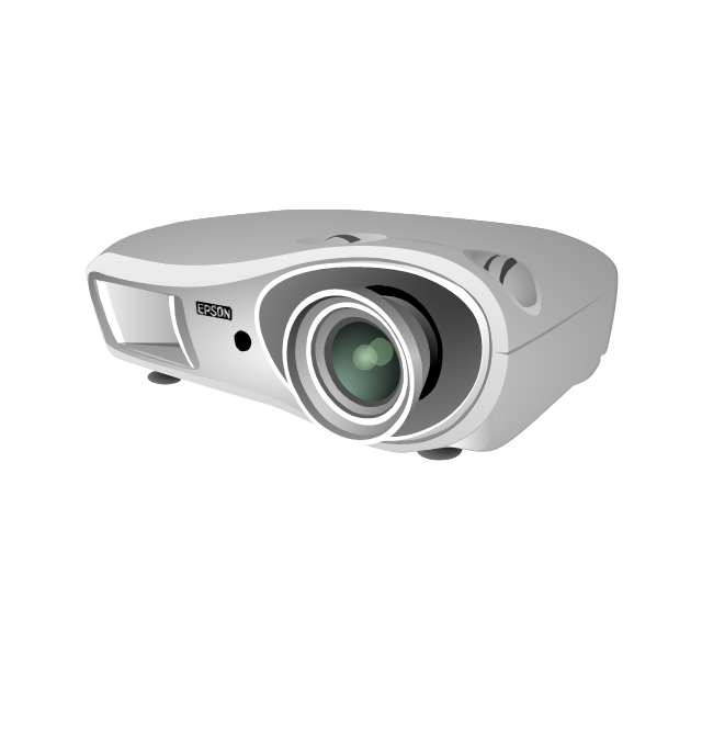
The vector stencils library "Computer peripheral devices" contains 18 clipart images of computer peripheral devices and equipment for drawing network diagrams.
"A peripheral is a device that is connected to a host computer, but not an integral part of it. It expands the host's capabilities but does not form part of the core computer architecture. It is often, but not always, partially or completely dependent on the host.
There are three different types of peripherals:
(1) Input, used to interact with, or send data to the computer (mouse, keyboards, etc.).
(2) Output, which provides output to the user from the computer (monitors, printers, etc.).
(3) Storage, which stores data processed by the computer (hard drives, flash drives, etc.)" [Peripheral. Wikipedia]
The clip art example "Computer peripheral devices - Vector stencils library" was created using the ConceptDraw PRO diagramming and vector drawing software extended with the Computer and Networks solution from the Computer and Networks area of ConceptDraw Solution Park.
Uninterruptible power supply
Webcam
Keyboard
Optical mouse

Computer speakers
Headphones

VoIP phone
Apple Keyboard
Apple Mouse

LCD projector
Port adapter
Airport Express
Joystick
Webcam
Video projector
The vector stencils library "Cisco switches and hubs" contains 26 symbols of Cisco switches and hubs for drawing computer network diagrams.
"A switch is a device used on a computer network to physically connect devices together. Multiple cables can be connected to a switch to enable networked devices to communicate with each other. Switches manage the flow of data across a network by only transmitting a received message to the device for which the message was intended. Each networked device connected to a switch can be identified using a MAC address, allowing the switch to regulate the flow of traffic. This maximises security and efficiency of the network. Because of these features, a switch is often considered more "intelligent" than a network hub. Hubs neither provide security, or identification of connected devices. This means that messages have to be transmitted out of every port of the hub, greatly degrading the efficiency of the network." [Network switch. Wikipedia]
"An Ethernet hub, active hub, network hub, repeater hub, multiport repeater or hub is a device for connecting multiple Ethernet devices together and making them act as a single network segment. It has multiple input/ output (I/ O) ports, in which a signal introduced at the input of any port appears at the output of every port except the original incoming. A hub works at the physical layer (layer 1) of the OSI model. The device is a form of multiport repeater. Repeater hubs also participate in collision detection, forwarding a jam signal to all ports if it detects a collision." [Ethernet hub. Wikipedia]
The symbols example "Cisco switches and hubs - Vector stencils library" was created using the ConceptDraw PRO diagramming and vector drawing software extended with the Cisco Network Diagrams solution from the Computer and Networks area of ConceptDraw Solution Park.
www.conceptdraw.com/ solution-park/ computer-networks-cisco
Cisco hub

100BaseT hub

Small hub

Workgroup switch

Workgroup switch, subdued

Voice-enabled workgroup switch

ATM switch

LAN2LAN switch

ISDN switch

MGX 8000 multiservice switch

Multilayer switch with Si

Multilayer switch

Multilayer switch with Si, subdued

Program switch

Data center switch

Voice-enabled ATM switch

IP DSL switch

Content switch

Content service switch 1100

Virtual layer switch

Layer 2 remote switch

Server switch

Multilayer remote switch

Multifabric server switch

Access gateway

Long-Reach CPE

Network Visualization with ConceptDraw PRO

Network wiring cable. Computer and Network Examples

The vector stencils library "Cisco telepresence" contains 8 symbols of videoconference and telepresence equipment for drawing Cisco computer network diagrams.
"Videoconferencing is the conduct of a videoconference (also known as a video conference or videoteleconference) by a set of telecommunication technologies which allow two or more locations to communicate by simultaneous two-way video and audio transmissions. It has also been called 'visual collaboration' and is a type of groupware. ...
The core technology used in a videoconferencing system is digital compression of audio and video streams in real time. The hardware or software that performs compression is called a codec (coder/ decoder). Compression rates of up to 1:500 can be achieved. The resulting digital stream of 1s and 0s is subdivided into labeled packets, which are then transmitted through a digital network of some kind (usually ISDN or IP). The use of audio modems in the transmission line allow for the use of POTS, or the Plain Old Telephone System, in some low-speed applications, such as videotelephony, because they convert the digital pulses to/ from analog waves in the audio spectrum range.
The other components required for a videoconferencing system include:
(1) Video input : video camera or webcam.
(2) Video output: computer monitor, television or projector.
(3) Audio input: microphones, CD/ DVD player, cassette player, or any other source of PreAmp audio outlet.
(4) Audio output: usually loudspeakers associated with the display device or telephone.
(5) Data transfer: analog or digital telephone network, LAN or Internet.
(6) Computer: a data processing unit that ties together the other components, does the compressing and decompressing, and initiates and maintains the data linkage via the network." [Videoconferencing. Wikipedia]
The symbols example "Cisco telepresence - Vector stencils library" was created using the ConceptDraw PRO diagramming and vector drawing software extended with the Cisco Network Diagrams solution from the Computer and Networks area of ConceptDraw Solution Park.
www.conceptdraw.com/ solution-park/ computer-networks-cisco
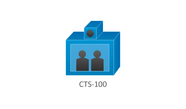
CTS-100
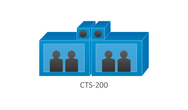
CTS-200
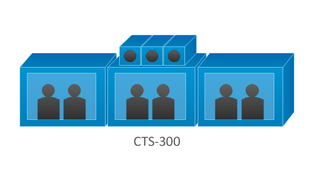
CTS-300
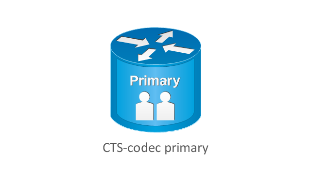
CTS-codec primary
CTS-codec secondary
TP MCU
Cisco telepresence manager
MCU
Internet Group Management Protocol (IGMP). Computer and Network Examples

"A logic gate is an idealized or physical device implementing a Boolean function, that is, it performs a logical operation on one or more logical inputs, and produces a single logical output. Depending on the context, the term may refer to an ideal logic gate, one that has for instance zero rise time and unlimited fan-out, or it may refer to a non-ideal physical device...
Logic gates are primarily implemented using diodes or transistors acting as electronic switches, but can also be constructed using electromagnetic relays (relay logic), fluidic logic, pneumatic logic, optics, molecules, or even mechanical elements. With amplification, logic gates can be cascaded in the same way that Boolean functions can be composed, allowing the construction of a physical model of all of Boolean logic, and therefore, all of the algorithms and mathematics that can be described with Boolean logic.
Logic circuits include such devices as multiplexers, registers, arithmetic logic units (ALUs), and computer memory, all the way up through complete microprocessors, which may contain more than 100 million gates. In practice, the gates are made from field-effect transistors (FETs), particularly MOSFETs (metal–oxide–semiconductor field-effect transistors).
Compound logic gates AND-OR-Invert (AOI) and OR-AND-Invert (OAI) are often employed in circuit design because their construction using MOSFETs is simpler and more efficient than the sum of the individual gates.
In reversible logic, Toffoli gates are used." [Logic gate. Wikipedia]
The logic gate diagram template for the ConceptDraw PRO diagramming and vector drawing software is included in the Electrical Engineering solution from the Engineering area of ConceptDraw Solution Park.
Logic gate diagram

Accounting Flowchart Symbols

Circuits and Logic Diagram Software

Activity Network Diagram Method

Restaurant Floor Plans

Functional Block Diagram

- Examples Of Input Devices Of Computer
- Examples Of Computer Input Device
- Hardware And Software Devices Of Computer
- Network Visualization with ConceptDraw PRO | Hardware Input And ...
- The Diagram Of Input Device
- Local area network (LAN). Computer and Network Examples ...
- How to Draw a Computer Network Diagrams | Process Flowchart ...
- Cisco LAN fault-tolerance system - diagram
- Examples Of Input Devices
- Telecommunication Network Diagrams | How to Draw a Computer ...
- Computer Lan
- How to Draw a Computer Network Diagrams | Network Diagram ...
- How to Draw a Computer Network Diagrams | Telecommunication ...
- Cisco LAN. Cisco icons, shapes, stencils and symbols | Cisco LAN ...
- Computer peripheral devices - Vector stencils library | Control ...
- Computer Network Diagrams | Network Diagram Software LAN ...
- Cisco LAN fault-tolerance system - diagram | Cisco Design | Cisco ...
- IDEF1X Standard | Computer network system design diagram ...
- Cisco Network Diagrams | Cisco LAN fault-tolerance system ...
- Explain The Diagram Of LAN