This vector stencils library contains 47 SysML activity diagram symbols.
Use it to design your SysML activity diagrams using ConceptDraw PRO diagramming and vector drawing software.
"Activity diagrams are constructed from a limited number of shapes, connected with arrows. The most important shape types:
- rounded rectangles represent actions;
- diamonds represent decisions;
- bars represent the start (split) or end (join) of concurrent activities;
- a black circle represents the start (initial state) of the workflow;
- an encircled black circle represents the end (final state).
Arrows run from the start towards the end and represent the order in which activities happen." [Activity diagram. Wikipedia]
The vector stencils library "Activity diagram" is included in the SysML solution from the Software Development area of ConceptDraw Solution Park.
Action

Call behavior action

Accept event action

Accept time event action

Send signal action

Activity

Activity final node

Flow final node

Activity parameter node

Control operator node

Control operator - frame

Decision/Merge node

Fork/Join node

Initial node

isControl

isStream

isStream 2

isStream 3

Local precondition

Local postcondition

NoBuffer

Object node

Object node 2

Optional

Optional 2

OverWrite

Parameter set

Parameter set 2

Probability

Probability 2

Rate

Rate 2

Rate 3

Rate 4

Rate 5

Rate 6

Control flow

Control flow 2

Object flow

Object flow 2

Probability path

Rate path

In block definition diagram, activity, association

Activity partition

Activity partition - action

Interruptible activity region

Structured activity node

This vector stencils library contains 13 symbols for drawing UML interaction overview diagrams.
Interaction
Initial Node

Decision/Merge Node

Receive Signal Node

Fork/Join Node
Final Node

Lifeline
Message
Control Flow
Constraint

Parallel Control Flow

Smart Connector
Note
This vector stencils library contains 47 SysML activity diagram symbols.
Use it to design your SysML activity diagrams using ConceptDraw PRO diagramming and vector drawing software.
"Activity diagrams are constructed from a limited number of shapes, connected with arrows. The most important shape types:
- rounded rectangles represent actions;
- diamonds represent decisions;
- bars represent the start (split) or end (join) of concurrent activities;
- a black circle represents the start (initial state) of the workflow;
- an encircled black circle represents the end (final state).
Arrows run from the start towards the end and represent the order in which activities happen." [Activity diagram. Wikipedia]
The vector stencils library "Activity diagram" is included in the SysML solution from the Software Development area of ConceptDraw Solution Park.
Use it to design your SysML activity diagrams using ConceptDraw PRO diagramming and vector drawing software.
"Activity diagrams are constructed from a limited number of shapes, connected with arrows. The most important shape types:
- rounded rectangles represent actions;
- diamonds represent decisions;
- bars represent the start (split) or end (join) of concurrent activities;
- a black circle represents the start (initial state) of the workflow;
- an encircled black circle represents the end (final state).
Arrows run from the start towards the end and represent the order in which activities happen." [Activity diagram. Wikipedia]
The vector stencils library "Activity diagram" is included in the SysML solution from the Software Development area of ConceptDraw Solution Park.
Action
Call behavior action
Accept event action
Accept time event action
Send signal action
Activity
Activity final node
Flow final node
Activity parameter node
Control operator node
Control operator - frame
Decision/Merge node
Fork/Join node
Initial node
isControl
isStream
isStream 2
isStream 3
Local precondition
Local postcondition
NoBuffer
Object node
Object node 2
Optional
Optional 2
OverWrite
Parameter set
Parameter set 2
Probability
Probability 2
Rate
Rate 2
Rate 3
Rate 4
Rate 5
Rate 6
Control flow
Control flow 2
Object flow
Object flow 2
Probability path
Rate path
In block definition diagram, activity, association
Activity partition
Activity partition - action
Interruptible activity region
Structured activity node
UML Activity Diagram. Design Elements


UML Interaction Overview Diagram. Design Elements

This purchase order processing UML activity diagram was created on the base of activity diagram from the software architecture documentation wiki of the Software Engineering Institute (SEI) of Carnegie Mellon University (CMU).
[wiki.sei.cmu.edu/ sad/ index.php/ Image:PurchaseOrderActivityDiagram.png]
"A purchase order (PO) is a commercial document and first official offer issued by a buyer to a seller, indicating types, quantities, and agreed prices for products or services. Acceptance of a purchase order by a seller forms a contract between the buyer and seller, so no contract exists until the purchase order is accepted. It is used to control the purchasing of products and services from external suppliers.
Creating a purchase order is typically the first step of the purchase to pay process in an ERP system." [Purchase order. Wikipedia]
This purchase order processing UML activity diagram example was created using the ConceptDraw PRO diagramming and vector drawing software extended with the ATM UML Diagrams solution from the Software Development area of ConceptDraw Solution Park.
UML activity diagram of purchase order processing

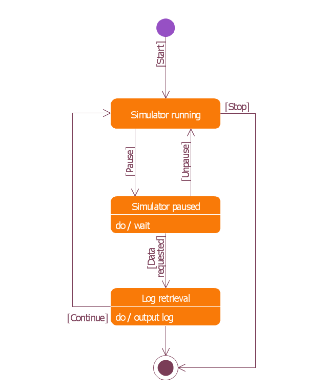
This example was redesigned from the Wikimedia Commons file: UML state diagram.png.
[commons.wikimedia.org/ wiki/ File:UML_ state_ diagram.png]
This file is licensed under the Creative Commons Attribution-Share Alike 3.0 Unported license. [creativecommons.org/ licenses/ by-sa/ 3.0/ deed.en]
"The StateMachine package defines a set of concepts that can be used for modeling discrete behavior through finite state transition systems. The state machine represents behavior as the state history of an object in terms of its transitions and states. The activities that are invoked during the transition, entry, and exit of the states are specified along with the associated event and guard conditions. Activities that are invoked while in the state are specified as “do Activities,” and can be either continuous or discrete. A composite state has nested states that can be sequential or concurrent.
The UML concept of protocol state machines is excluded from SysML to reduce the complexity of the language.
The standard UML state machine concept (called behavior state machines in UML) are thought to be sufficient for expressing protocols." [omg.org/ spec/ SysML/ 1.3/ PDF]
The example "State machine diagram" was drawn using the ConceptDraw PRO diagramming and vector drawing software extended with the SysML solution from the Software Development area of ConceptDraw Solution Park.
SysML state machine diagram
Activity on Node Network Diagramming Tool

Mesh Network Topology Diagram

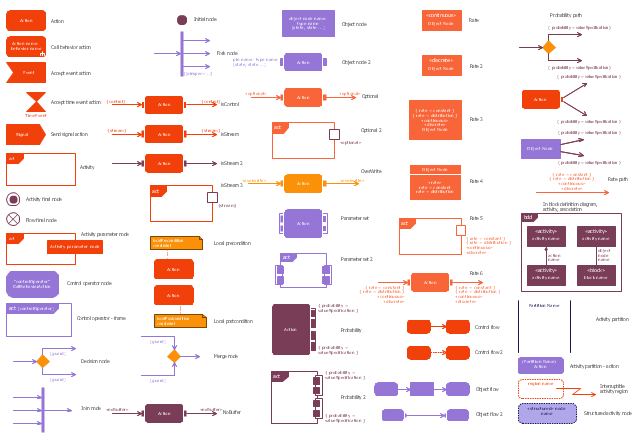
The vector stencils library "Activity diagram" contains 47 symbols.
Use it to design your SysML activity diagrams using ConceptDraw PRO diagramming and vector drawing software.
"Activity diagrams are constructed from a limited number of shapes, connected with arrows. The most important shape types:
- rounded rectangles represent actions;
- diamonds represent decisions;
- bars represent the start (split) or end (join) of concurrent activities;
- a black circle represents the start (initial state) of the workflow;
- an encircled black circle represents the end (final state).
Arrows run from the start towards the end and represent the order in which activities happen." [Activity diagram. Wikipedia]
The SysML shapes example "Design elements - Activity diagram" is included in the SysML solution from the Software Development area of ConceptDraw Solution Park.
SysML activity diagram symbols
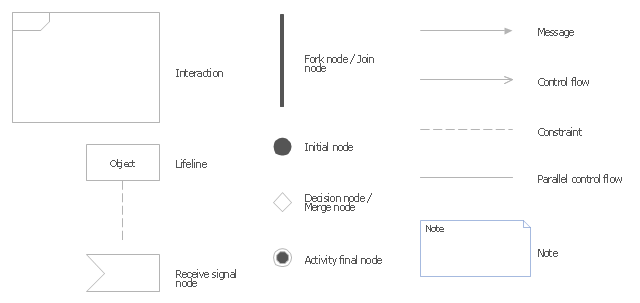
The vector stencils library "Bank UML interaction overview diagram" contains 11 shapes for drawing UML interaction overview diagrams.
Use it for object-oriented modeling of your bank information system.
"The interaction overview diagram is similar to the activity diagram, in that both visualize a sequence of activities. The difference is that, for an interaction overview, each individual activity is pictured as a frame which can contain a nested interaction diagrams. ...
The other notation elements for interaction overview diagrams are the same as for activity diagrams. These include initial, final, decision, merge, fork and join nodes. The two new elements in the interaction overview diagrams are the "interaction occurrences" and "interaction elements"." [Interaction overview diagram. Wikipedia]
This example of UML interaction overview diagram symbols for the ConceptDraw PRO diagramming and vector drawing software is included in the ATM UML Diagrams solution from the Software Development area of ConceptDraw Solution Park.
UML interaction overview diagram symbols
Activity Network Diagram Method

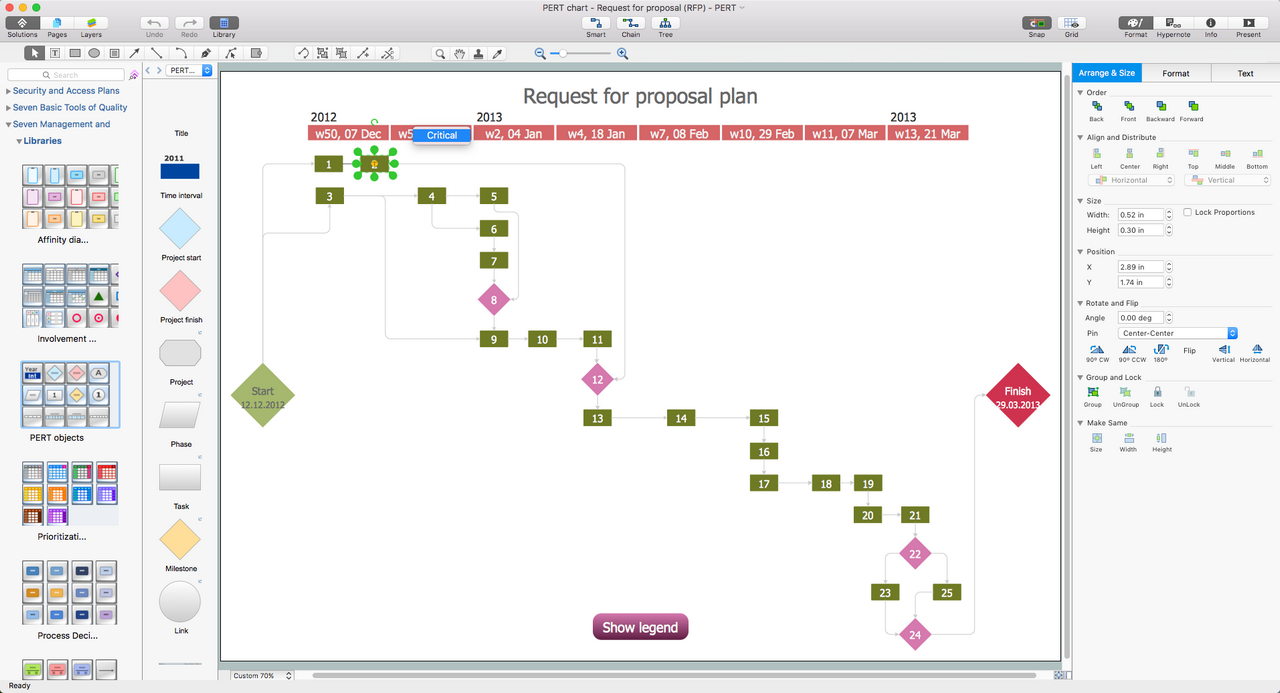
PERT Chart Software
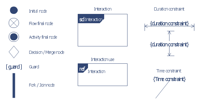
The vector stencils library "UML interaction overview diagrams" contains 13 symbols for the ConceptDraw PRO diagramming and vector drawing software.
"Interaction Overview Diagram is one of the fourteen types of diagrams of the Unified Modeling Language (UML), which can picture a control flow with nodes that can contain interaction diagrams.
The interaction overview diagram is similar to the activity diagram, in that both visualize a sequence of activities. The difference is that, for an interaction overview, each individual activity is pictured as a frame which can contain a nested interaction diagrams." [Interaction overview diagram. Wikipedia]
"Interaction diagrams.
Interaction diagrams, a subset of behavior diagrams, emphasize the flow of control and data among the things in the system being modeled:
(1) Communication diagram: shows the interactions between objects or parts in terms of sequenced messages. They represent a combination of information taken from Class, Sequence, and Use Case Diagrams describing both the static structure and dynamic behavior of a system.
(2) Interaction overview diagram: provides an overview in which the nodes represent interaction diagrams.
(3) Sequence diagram: shows how objects communicate with each other in terms of a sequence of messages. Also indicates the lifespans of objects relative to those messages.
(4) Timing diagrams: a specific type of interaction diagram where the focus is on timing constraints." [Unified Modeling Language. Wikipedia]
The example "Design elements - UML interaction overview diagrams" is included in the Rapid UML solution from the Software Development area of ConceptDraw Solution Park.
UML interaction overview diagram symbols
- Vector stencils library - Activity diagram
- UML interaction overview diagrams
- Initial
- Initial And Final Action State
- Activity on Node Network Diagramming Tool | Program Evaluation ...
- UML Activity Diagram. Design Elements | Vector stencils library ...
- UML Activity Diagram | Activity Network Diagram Method | Activity on ...
- UML interaction overview diagrams
- Activity on Node Network Diagramming Tool | Program Evaluation ...
- Vector stencils library - Activity diagram | UML Activity Diagram ...
- UML Activity Diagram | Vector stencils library - Activity diagram ...
- Vector stencils library - State machine diagram | Vector stencils ...
- Vector stencils library - State machine diagram | Vector stencils ...
- Activity on Node Network Diagramming Tool | UML Deployment ...
- Activity on Node Network Diagramming Tool | Program Evaluation ...
- Activity on Node Network Diagramming Tool | Network Analysis ...
- Final object schematic - IDEF3 diagram | Vector stencils library ...
- Initial State
- Activity Diagram Initial Start
- UML State Machine Diagram.Design Elements | Vector stencils ...