This vector stencils library contains 13 symbols for drawing UML interaction overview diagrams.
Interaction
Initial Node

Decision/Merge Node

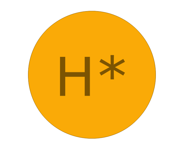
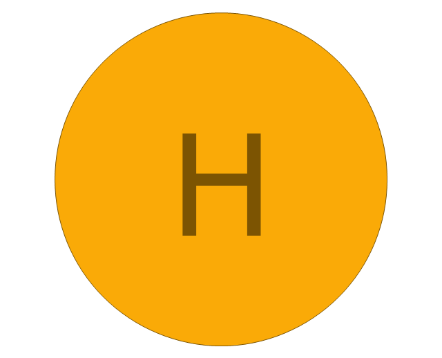
Receive Signal Node

Fork/Join Node

Final Node

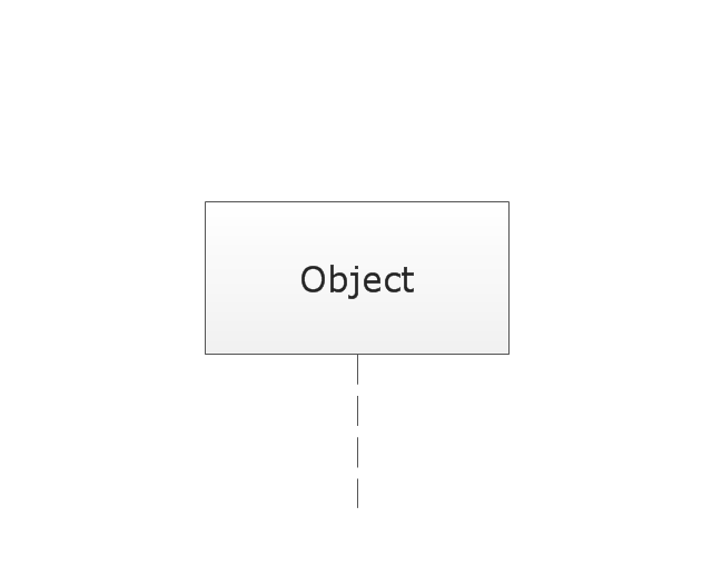
Lifeline
Message
Control Flow
Constraint

Parallel Control Flow

Smart Connector
Note
This vector stencils library contains 13 symbols for drawing UML interaction overview diagrams.
Interaction

Initial Node

Decision/Merge Node

Receive Signal Node

Fork/Join Node

Final Node

Lifeline
Message
Control Flow
Constraint

Parallel Control Flow

Smart Connector
Note
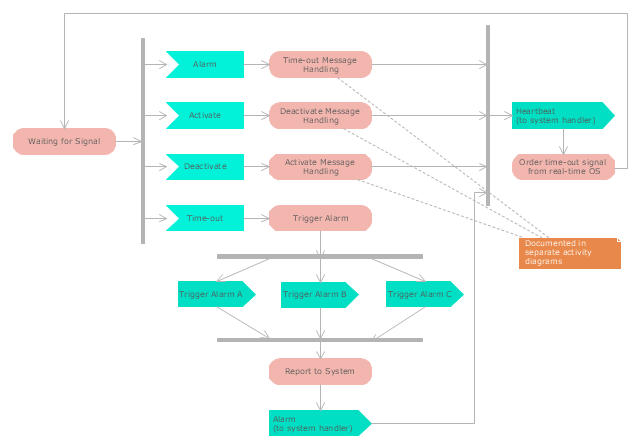
"Alarm triggers.
The individual triggers for a car alarm vary widely, depending on the make and model of the vehicle, and the brand and model of the alarm itself (for aftermarket alarms). Since aftermarket alarms are designed to be universal (i.e., compatible with all 12 volt negative ground electrical systems as opposed to one carmaker's vehicles), these commonly have trigger inputs that the installer/ vehicle owner chooses not to connect, which additionally determines what will set the alarm off." [Car alarm. Wikipedia]
The UML activity diagram example " Alarm trigger processing" was created using the ConceptDraw PRO diagramming and vector drawing software extended with the Rapid UML solution from the Software Development area of ConceptDraw Solution Park.
UML activity diagram
This vector stencils library contains 47 SysML symbols.
Use it to design your state machine diagrams using ConceptDraw PRO diagramming and vector drawing software.
"The state diagram in the Unified Modeling Language is essentially a Harel statechart with standardized notation, which can describe many systems, from computer programs to business processes. In UML 2 the name has been changed to State Machine Diagram. The following are the basic notational elements that can be used to make up a diagram:
- Filled circle, representing to the initial state
- Hollow circle containing a smaller filled circle, indicating the final state (if any)
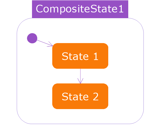
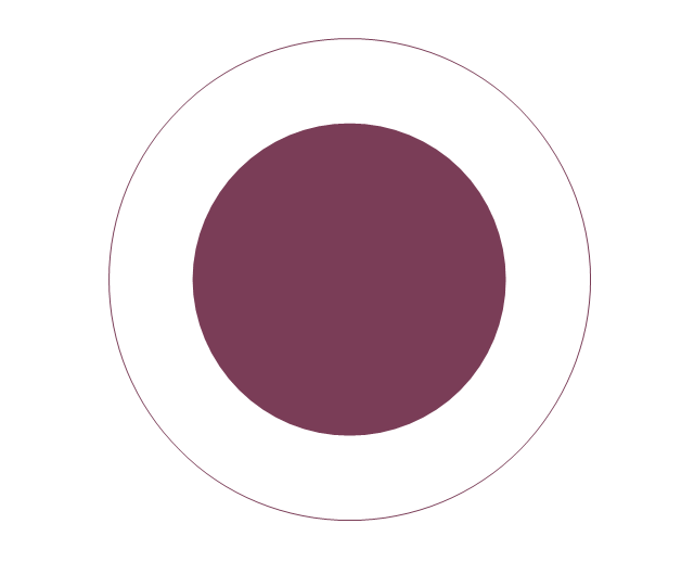
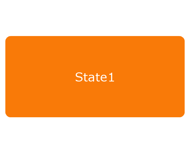
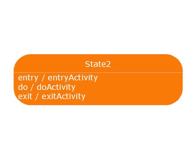
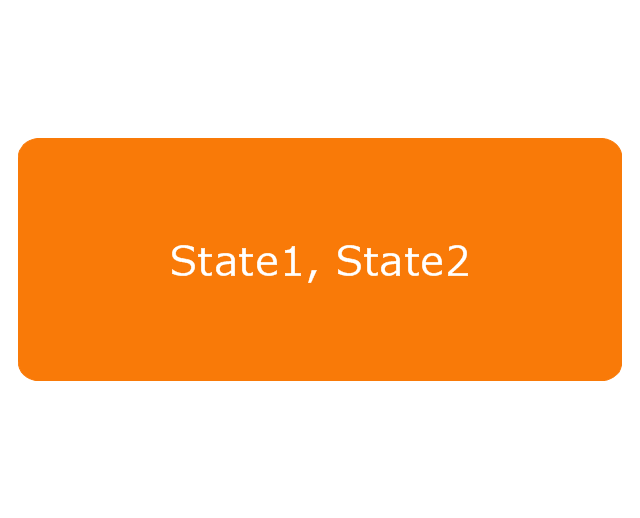
- Rounded rectangle, denoting a state. Top of the rectangle contains a name of the state. Can contain a horizontal line in the middle, below which the activities that are done in that state are indicated
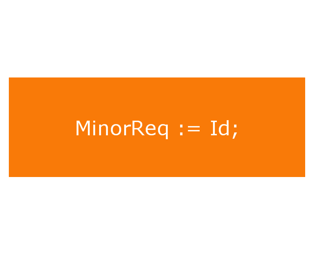
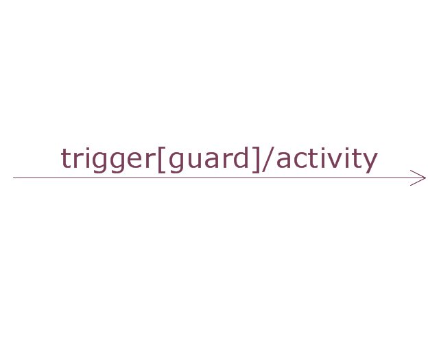
- Arrow, denoting transition. The name of the event (if any) causing this transition labels the arrow body. A guard expression may be added before a "/ " and enclosed in square-brackets ( eventName[guardExpression] ), denoting that this expression must be true for the transition to take place. If an action is performed during this transition, it is added to the label following a "/ " ( eventName[guardExpression]/ action ).
- Thick horizontal line with either x>1 lines entering and 1 line leaving or 1 line entering and x>1 lines leaving. These denote join/ fork, respectively." [State diagram (UML). Wikipedia]
The vector stencils library "State machine diagram" is included in the SysML solution from the Software Development area of ConceptDraw Solution Park.
Use it to design your state machine diagrams using ConceptDraw PRO diagramming and vector drawing software.
"The state diagram in the Unified Modeling Language is essentially a Harel statechart with standardized notation, which can describe many systems, from computer programs to business processes. In UML 2 the name has been changed to State Machine Diagram. The following are the basic notational elements that can be used to make up a diagram:
- Filled circle, representing to the initial state
- Hollow circle containing a smaller filled circle, indicating the final state (if any)
- Rounded rectangle, denoting a state. Top of the rectangle contains a name of the state. Can contain a horizontal line in the middle, below which the activities that are done in that state are indicated
- Arrow, denoting transition. The name of the event (if any) causing this transition labels the arrow body. A guard expression may be added before a "/ " and enclosed in square-brackets ( eventName[guardExpression] ), denoting that this expression must be true for the transition to take place. If an action is performed during this transition, it is added to the label following a "/ " ( eventName[guardExpression]/ action ).
- Thick horizontal line with either x>1 lines entering and 1 line leaving or 1 line entering and x>1 lines leaving. These denote join/ fork, respectively." [State diagram (UML). Wikipedia]
The vector stencils library "State machine diagram" is included in the SysML solution from the Software Development area of ConceptDraw Solution Park.
Choice pseudostate

Composite state
Entry point
Exit point
Final state
History, deep pseudostate
History, shallow pseudostate
Initial pseudostate

Junction pseudostate

Receive signal action
Send signal action
Action
Region
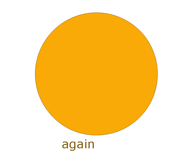
Simple state
Simple state 2
State list
State machine
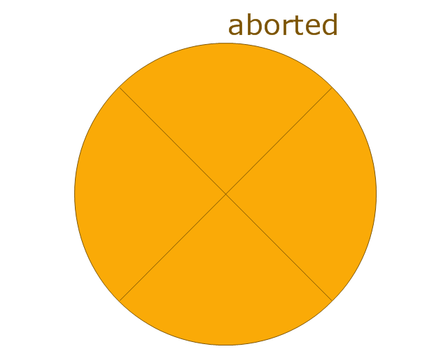
Terminate node

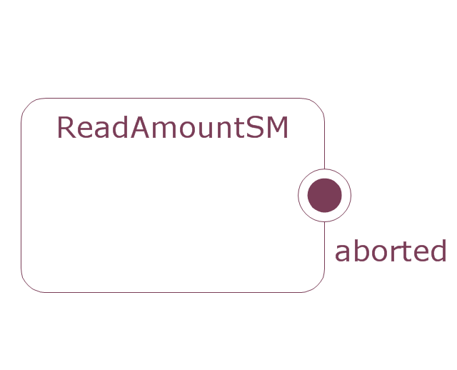
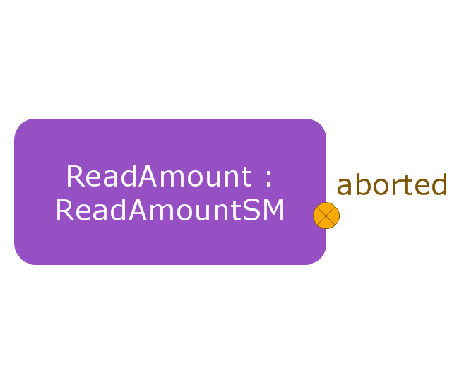
Submachine state
Transition
This vector stencils library contains 13 symbols for drawing UML interaction overview diagrams.
Interaction
Initial Node
Decision/Merge Node
Receive Signal Node
Fork/Join Node
Final Node
Lifeline
Message
Control Flow
Constraint
Parallel Control Flow
Smart Connector
Note
This vector stencils library contains 47 SysML symbols.
Use it to design your state machine diagrams using ConceptDraw PRO diagramming and vector drawing software.
"The state diagram in the Unified Modeling Language is essentially a Harel statechart with standardized notation, which can describe many systems, from computer programs to business processes. In UML 2 the name has been changed to State Machine Diagram. The following are the basic notational elements that can be used to make up a diagram:
- Filled circle, representing to the initial state
- Hollow circle containing a smaller filled circle, indicating the final state (if any)
- Rounded rectangle, denoting a state. Top of the rectangle contains a name of the state. Can contain a horizontal line in the middle, below which the activities that are done in that state are indicated
- Arrow, denoting transition. The name of the event (if any) causing this transition labels the arrow body. A guard expression may be added before a "/ " and enclosed in square-brackets ( eventName[guardExpression] ), denoting that this expression must be true for the transition to take place. If an action is performed during this transition, it is added to the label following a "/ " ( eventName[guardExpression]/ action ).
- Thick horizontal line with either x>1 lines entering and 1 line leaving or 1 line entering and x>1 lines leaving. These denote join/ fork, respectively." [State diagram (UML). Wikipedia]
The vector stencils library "State machine diagram" is included in the SysML solution from the Software Development area of ConceptDraw Solution Park.
Choice pseudostate
Composite state
Entry point
Exit point
Final state
History, deep pseudostate
History, shallow pseudostate
Initial pseudostate
Junction pseudostate
Receive signal action
Send signal action
Action
Region
Simple state
Simple state 2
State list
State machine
Terminate node
Submachine state
Transition
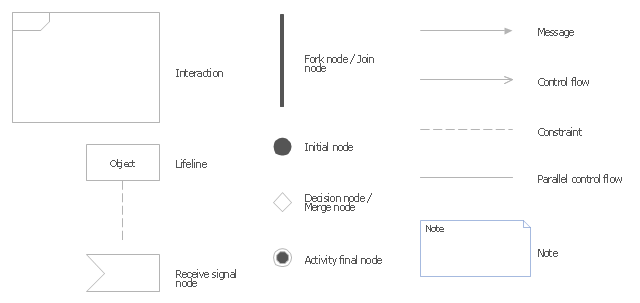
The vector stencils library "UML interaction overview diagrams" contains 13 symbols for the ConceptDraw PRO diagramming and vector drawing software.
"Interaction Overview Diagram is one of the fourteen types of diagrams of the Unified Modeling Language (UML), which can picture a control flow with nodes that can contain interaction diagrams.
The interaction overview diagram is similar to the activity diagram, in that both visualize a sequence of activities. The difference is that, for an interaction overview, each individual activity is pictured as a frame which can contain a nested interaction diagrams." [Interaction overview diagram. Wikipedia]
"Interaction diagrams.
Interaction diagrams, a subset of behavior diagrams, emphasize the flow of control and data among the things in the system being modeled:
(1) Communication diagram: shows the interactions between objects or parts in terms of sequenced messages. They represent a combination of information taken from Class, Sequence, and Use Case Diagrams describing both the static structure and dynamic behavior of a system.
(2) Interaction overview diagram: provides an overview in which the nodes represent interaction diagrams.
(3) Sequence diagram: shows how objects communicate with each other in terms of a sequence of messages. Also indicates the lifespans of objects relative to those messages.
(4) Timing diagrams: a specific type of interaction diagram where the focus is on timing constraints." [Unified Modeling Language. Wikipedia]
The example "Design elements - UML interaction overview diagrams" is included in the Rapid UML solution from the Software Development area of ConceptDraw Solution Park.
UML interaction overview diagram symbols
UML Activity Diagram. Design Elements


UML State Machine Diagram.Design Elements

UML Interaction Overview Diagram. Design Elements

The vector stencils library "UML interaction overview diagrams" contains 13 symbols for the ConceptDraw PRO diagramming and vector drawing software.
"Interaction Overview Diagram is one of the fourteen types of diagrams of the Unified Modeling Language (UML), which can picture a control flow with nodes that can contain interaction diagrams.
The interaction overview diagram is similar to the activity diagram, in that both visualize a sequence of activities. The difference is that, for an interaction overview, each individual activity is pictured as a frame which can contain a nested interaction diagrams." [Interaction overview diagram. Wikipedia]
"Interaction diagrams.
Interaction diagrams, a subset of behavior diagrams, emphasize the flow of control and data among the things in the system being modeled:
(1) Communication diagram: shows the interactions between objects or parts in terms of sequenced messages. They represent a combination of information taken from Class, Sequence, and Use Case Diagrams describing both the static structure and dynamic behavior of a system.
(2) Interaction overview diagram: provides an overview in which the nodes represent interaction diagrams.
(3) Sequence diagram: shows how objects communicate with each other in terms of a sequence of messages. Also indicates the lifespans of objects relative to those messages.
(4) Timing diagrams: a specific type of interaction diagram where the focus is on timing constraints." [Unified Modeling Language. Wikipedia]
The example "Design elements - UML interaction overview diagrams" is included in the Rapid UML solution from the Software Development area of ConceptDraw Solution Park.
"Interaction Overview Diagram is one of the fourteen types of diagrams of the Unified Modeling Language (UML), which can picture a control flow with nodes that can contain interaction diagrams.
The interaction overview diagram is similar to the activity diagram, in that both visualize a sequence of activities. The difference is that, for an interaction overview, each individual activity is pictured as a frame which can contain a nested interaction diagrams." [Interaction overview diagram. Wikipedia]
"Interaction diagrams.
Interaction diagrams, a subset of behavior diagrams, emphasize the flow of control and data among the things in the system being modeled:
(1) Communication diagram: shows the interactions between objects or parts in terms of sequenced messages. They represent a combination of information taken from Class, Sequence, and Use Case Diagrams describing both the static structure and dynamic behavior of a system.
(2) Interaction overview diagram: provides an overview in which the nodes represent interaction diagrams.
(3) Sequence diagram: shows how objects communicate with each other in terms of a sequence of messages. Also indicates the lifespans of objects relative to those messages.
(4) Timing diagrams: a specific type of interaction diagram where the focus is on timing constraints." [Unified Modeling Language. Wikipedia]
The example "Design elements - UML interaction overview diagrams" is included in the Rapid UML solution from the Software Development area of ConceptDraw Solution Park.
UML interaction overview diagram symbols
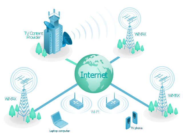
Network Glossary Definition


"Mobile IPTV is a technology that enables users to transmit and receive multimedia traffic including television signal, video, audio, text and graphic services through IP-based the wired and wireless networks with support for Quality of Service/ QoE, security, mobility, and interactive functions. Through Mobile IPTV, users can enjoy IPTV services anywhere and even while on the move." [Mobile IPTV. Wikipedia]
This mobile web-based TV network diagram example was created using the ConceptDraw PRO diagramming and vector drawing software extended with the Telecommunication Network Diagrams solution from the Computer and Networks area of ConceptDraw Solution Park.
This mobile web-based TV network diagram example was created using the ConceptDraw PRO diagramming and vector drawing software extended with the Telecommunication Network Diagrams solution from the Computer and Networks area of ConceptDraw Solution Park.
Mobile IP-based TV diagram
Value Stream Mapping Icons
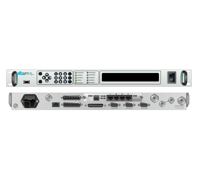
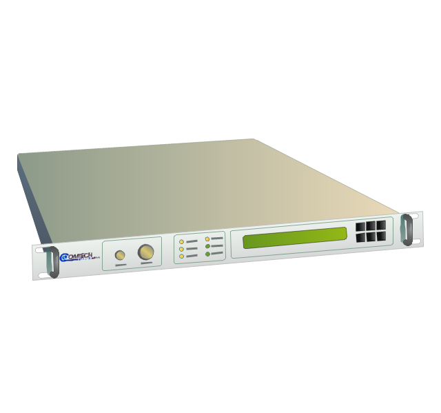
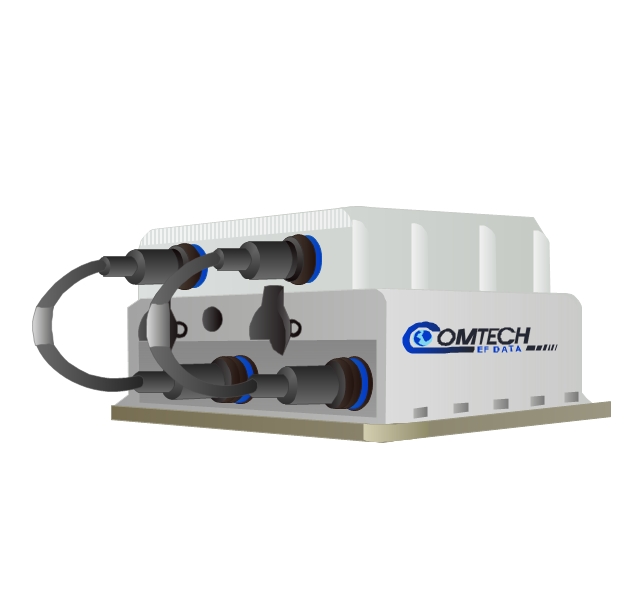
The vector stencils library "Comtech" contains 9 icons of Comtech devices for drawing computer network diagrams and telecommunication equipment layouts.
"Comtech EF Data Corporation ... communication solutions encompass Advanced VSAT Solutions, Modems, RAN & WAN Optimization, Network & Bandwidth Management, RF Products ... for fixed and mobile/ transportable satellite-based applications." [comtechefdata.com]
The clip art example "Comtech - Vector stencils library" was created using the ConceptDraw PRO diagramming and vector drawing software extended with the Telecommunication Network Diagrams solution from the Computer and Networks area of ConceptDraw Solution Park.
CDD-562L & CDD-562LEN dual IP demodulator
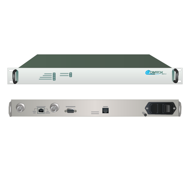
CDM-700G high-speed satellite modem
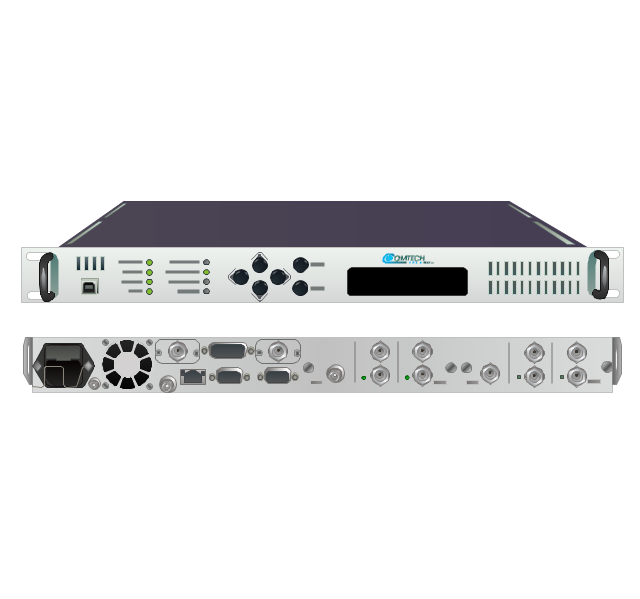
CDM-710G high-speed satellite modem
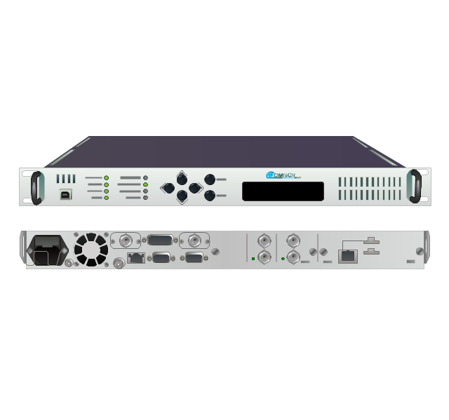
SLM-5650A satellite modem
UT-4505 series up converters
LPOD C- or Ku-band block up converters
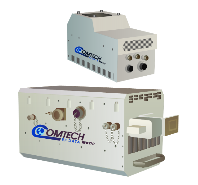
MBT-4000/ MBT-4000B outdoor multi-band RF transceiver
High-Power Outdoor C-, X- & Ku-band outdoor amplifier (HPOD)
-comtech---vector-stencils-library.png--diagram-flowchart-example.png)
Indoor solid state power amplifiers (SSPA)
-comtech---vector-stencils-library.png--diagram-flowchart-example.png)
- Send Signal
- Receive Signal State
- UML interaction overview diagrams
- Receive Signal Node
- Uml State Diagram Signal
- Vector stencils library - State machine diagram | UML State Machine ...
- Design elements - UML interaction overview diagrams ...
- Vector stencils library - State machine diagram | State machine ...
- Vector stencils library - State machine diagram | UML state machine ...
- Vector stencils library - State machine diagram
- UML activity diagram - Alarm trigger processing | Design elements ...
- Vector stencils library - Activity diagram | UML interaction overview ...
- UML activity diagram - Alarm trigger processing | Diagramming ...
- UML activity diagram - Alarm trigger processing | Windows 8 apps ...
- Entity-Relationship Diagram (ERD) with ConceptDraw PRO | UML ...
- Final object schematic - IDEF3 diagram | Vector stencils library ...
- UML State Machine Diagram.Design Elements
- Design elements - UML interaction overview diagrams
- Data Flow Diagram Model
- Expanded objects BPMN 1.2 - Vector stencils library | Vector stencils ...