The vector stencils library "Wireless networks" contains 82 icon symbols for drawing wireless computer network diagrams and equipment layout plans.
"A wireless network is any type of computer network that uses wireless data connections for connecting network nodes.
Wireless networking is a method by which homes, telecommunications networks and enterprise (business) installations avoid the costly process of introducing cables into a building, or as a connection between various equipment locations.
Wireless telecommunications networks are generally implemented and administered using radio communication. This implementation takes place at the physical level (layer) of the OSI model network structure.
Examples of wireless networks include cell phone networks, Wi-Fi local networks and terrestrial microwave networks." [Wireless network. Wikipedia]
The clip art example "Wireless networks - Vector stencils library" was created using the ConceptDraw PRO diagramming and vector drawing software extended with the Wireless Networks solution from the Computer and Networks area of ConceptDraw Solution Park.
www.conceptdraw.com/ solution-park/ wireless-networks
Building 1
Building 4
Coverage (Blue)
-wireless-networks---vector-stencils-library.png--diagram-flowchart-example.png)
Wireless Connectivity

Network Cloud

Cloud

Wi-Fi Access

Tree

Computer
Laptop Computer

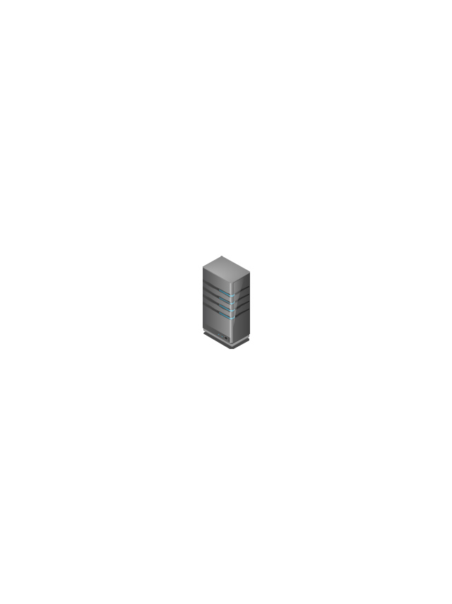
Server

Wireless Network Storage

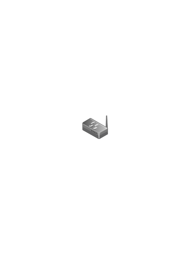
Router
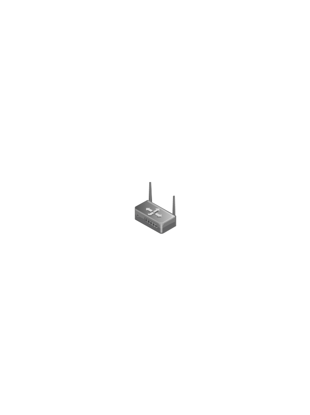
Wireless Router
Switch
Wireless Access Point
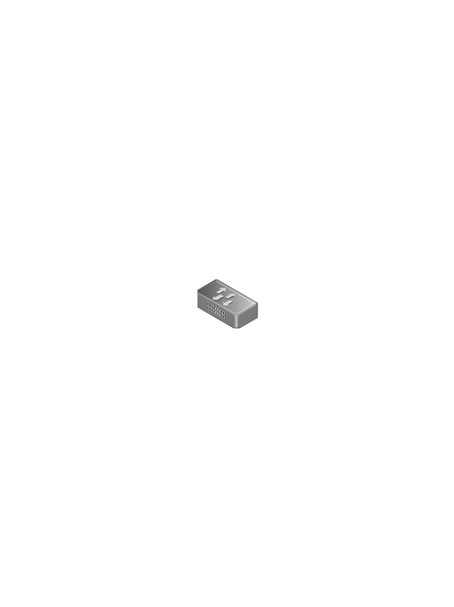
1U Hub Switch

2U Hub Switch
1U Server

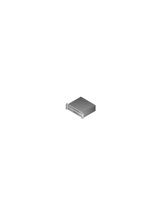
2U Server

3U Server

4U Server

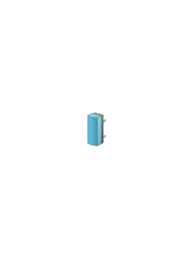
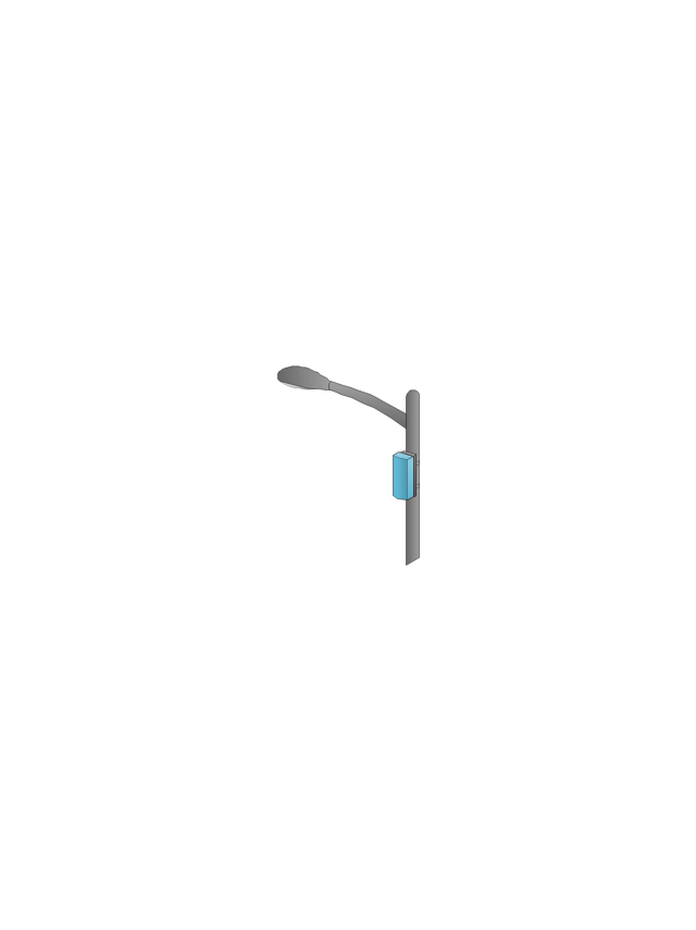
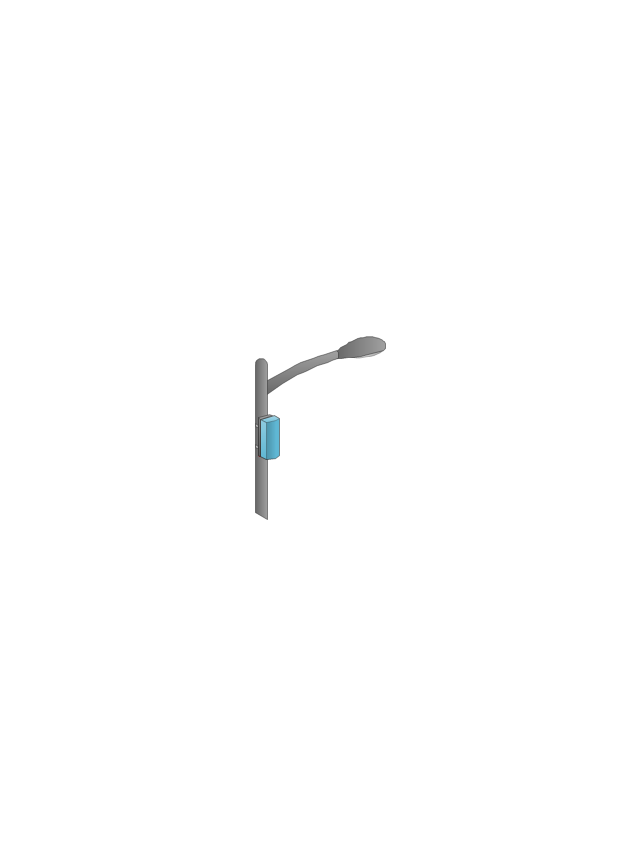
Outdoor Access Point

Indoor Access Point

Outdoor Wi-Fi Access Point

Access Point

Outdoor Mesh Node
Outdoor Mesh Node
Outdoor Access Node
Outdoor Access Node

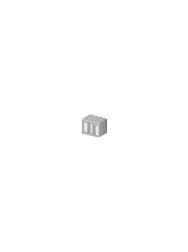
Base Station

Cellular Phone

Outdoor Mesh Node
Active Directory Server
Smart WLAN Controller

Smart WLAN Controller

Smart Wi-Fi Access Point
Indoor Wi-Fi Access Point

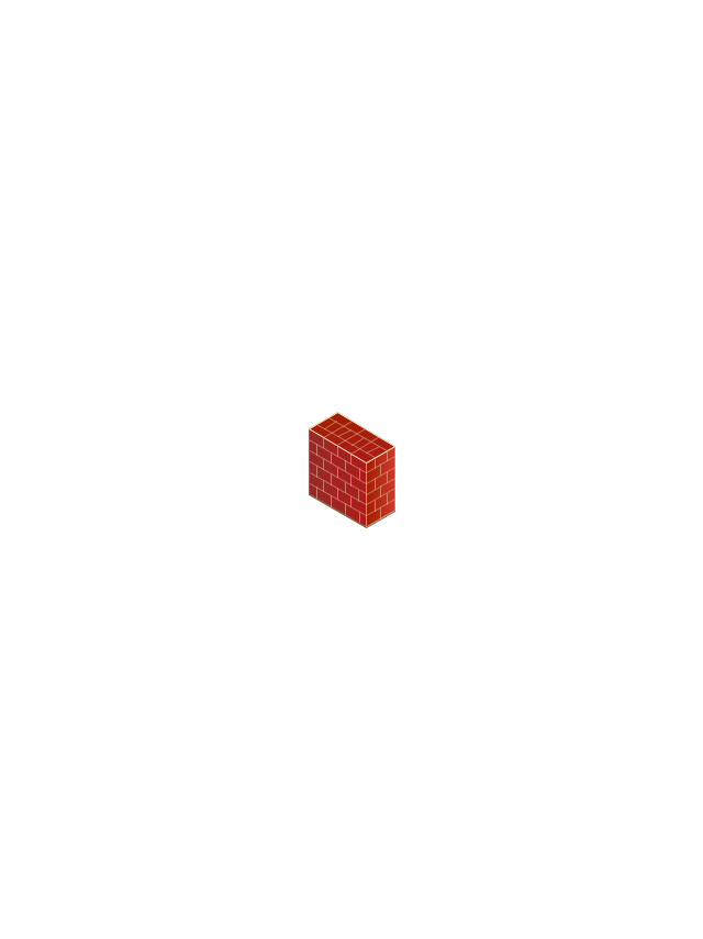
Firewall
Coverage (Yellow)
-wireless-networks---vector-stencils-library.png--diagram-flowchart-example.png)
Coverage (O-Shaped)
-wireless-networks---vector-stencils-library.png--diagram-flowchart-example.png)
Outdoor Mesh Node

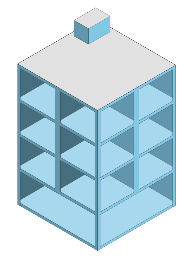
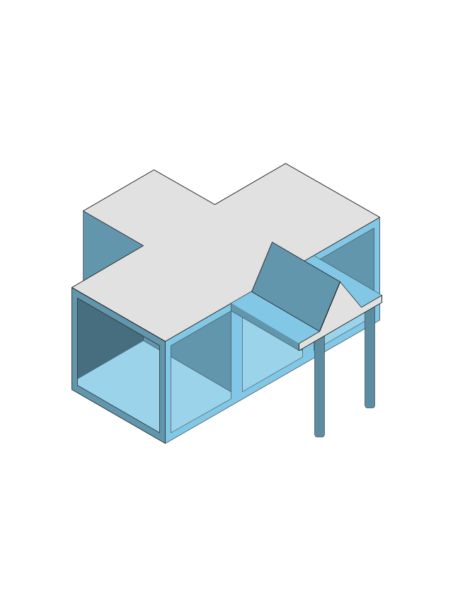
The vector stencils library "Bank UML deployment diagram" contains 10 shapes for drawing UML deployment diagrams.
Use it for object-oriented modeling of your bank information system.
"A deployment diagram in the Unified Modeling Language models the physical deployment of artifacts on nodes. To describe a web site, for example, a deployment diagram would show what hardware components ("nodes") exist (e.g., a web server, an application server, and a database server), what software components ("artifacts") run on each node (e.g., web application, database), and how the different pieces are connected (e.g. JDBC, REST, RMI).
The nodes appear as boxes, and the artifacts allocated to each node appear as rectangles within the boxes. Nodes may have subnodes, which appear as nested boxes. A single node in a deployment diagram may conceptually represent multiple physical nodes, such as a cluster of database servers.
There are two types of Nodes:
1. Device Node.
2. Execution Environment Node.
Device nodes are physical computing resources with processing memory and services to execute software, such as typical computers or mobile phones. An execution environment node (EEN) is a software computing resource that runs within an outer node and which itself provides a service to host and execute other executable software elements." [Deployment diagram. Wikipedia]
This example of UML deployment diagram symbols for the ConceptDraw PRO diagramming and vector drawing software is included in the ATM UML Diagrams solution from the Software Development area of ConceptDraw Solution Park.
UML deployment diagram symbols

This vector stencils library contains 47 SysML activity diagram symbols.
Use it to design your SysML activity diagrams using ConceptDraw PRO diagramming and vector drawing software.
"Activity diagrams are constructed from a limited number of shapes, connected with arrows. The most important shape types:
- rounded rectangles represent actions;
- diamonds represent decisions;
- bars represent the start (split) or end (join) of concurrent activities;
- a black circle represents the start (initial state) of the workflow;
- an encircled black circle represents the end (final state).
Arrows run from the start towards the end and represent the order in which activities happen." [Activity diagram. Wikipedia]
The vector stencils library "Activity diagram" is included in the SysML solution from the Software Development area of ConceptDraw Solution Park.
Action

Call behavior action

Accept event action

Accept time event action

Send signal action

Activity

Activity final node

Flow final node

Activity parameter node

Control operator node

Control operator - frame

Decision/Merge node

Fork/Join node

Initial node

isControl

isStream

isStream 2

isStream 3

Local precondition

Local postcondition

NoBuffer

Object node

Object node 2

Optional

Optional 2

OverWrite

Parameter set

Parameter set 2

Probability

Probability 2

Rate

Rate 2

Rate 3

Rate 4

Rate 5

Rate 6

Control flow

Control flow 2

Object flow

Object flow 2

Probability path

Rate path

In block definition diagram, activity, association

Activity partition

Activity partition - action

Interruptible activity region

Structured activity node

The vector stencils library "IDEF0 diagrams" contains 18 symbols for drawing IDEF0 function modeling diagrams using the ConceptDraw PRO diagramming and vector drawing software.
"The IDEF0 model ... is based on a simple syntax. Each activity is described by a verb-based label placed in a box. Inputs are shown as arrows entering the left side of the activity box while output are shown as exiting arrows on the right side of the box. Controls are displayed as arrows entering the top of the box and mechanisms are displayed as arrows entering from the bottom of the box. Inputs, Controls, Outputs, and Mechanisms are all referred to as concepts.
- Arrow : A directed line, composed of one or more arrow segments, that models an open channel or conduit conveying data or objects from source (no arrowhead) to use (with arrowhead). There are 4 arrow classes: Input Arrow, Output Arrow, Control Arrow, and Mechanism Arrow (includes Call Arrow). See Arrow Segment, Boundary Arrow, Internal Arrow.
- Box : A rectangle, containing a name and number, used to represent a function.
- Context : The immediate environment in which a function (or set of functions on a diagram) operates.
- Decomposition : The partitioning of a modeled function into its component functions.
- Fork : The junction at which an IDEF0 arrow segment (going from source to use) divides into two or more arrow segments. May denote unbundling of meaning.
- Function : An activity, process, or transformation (modeled by an IDEF0 box) identified by a verb or verb phrase that describes what must be accomplished.
- Join : The junction at which an IDEF0 arrow segment (going from source to use) merges with one or more other arrow segments to form a single arrow segment. May denote bundling of arrow segment meanings.
- Node : A box from which child boxes originate; a parent box. See Node Index, Node Tree, Node Number, Node Reference, Diagram Node Number." [IDEF0. Wikipedia]
The example "Design elements - IDEF0 diagram" is included in the IDEF0 Diagrams solution from the Software Development area of ConceptDraw Solution Park.
IDEF0 symbols

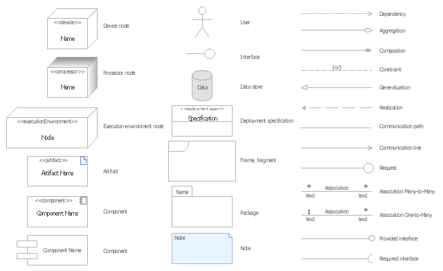
The vector stencils library "UML deployment diagrams" contains 31 symbols for the ConceptDraw PRO diagramming and vector drawing software.
"A deployment diagram in the Unified Modeling Language models the physical deployment of artifacts on nodes. ...
The nodes appear as boxes, and the artifacts allocated to each node appear as rectangles within the boxes. Nodes may have subnodes, which appear as nested boxes. A single node in a deployment diagram may conceptually represent multiple physical nodes, such as a cluster of database servers.
There are two types of Nodes.
(1) Device Node.
(2) Execution Environment Node." [Deployment diagram. Wikipedia]
The example "Design elements - UML deployment diagrams" is included in the Rapid UML solution from the Software Development area of ConceptDraw Solution Park.
UML deployment diagram symbols
- Activity on Node Network Diagramming Tool | Process Flowchart ...
- Activity on Node Network Diagramming Tool | Network Analysis ...
- Activity on Node Network Diagramming Tool | Program Evaluation ...
- Activity on Node Network Diagramming Tool | PERT chart ...
- Network Analysis Activity on Node | Activity on Node Network ...
- Activity on Node Network Diagramming Tool | ConceptDraw PRO ...
- Activity on Node Network Diagramming Tool | Activity Network ...
- Activity on Node Network Diagramming Tool | UML Sample Project ...
- Activity on Node Network Diagramming Tool | Influence Diagram ...
- Uml Deployment Diagram
- UML Activity Diagram | UML Sample Project | Activity on Node ...
- Activity on Node Network Diagramming Tool | Network Diagramming ...
- UML Activity Diagram | Activity on Node Network Diagramming Tool ...
- | | | Optical Node
- Activity on Node Network Diagramming Tool | UML Deployment ...
- Activity on Node Network Diagramming Tool | Examples of ...
- ConceptDraw PRO Network Diagram Tool | Activity on Node ...
- Activity on Node Network Diagramming Tool | Organizational Charts ...
- Activity on Node Network Diagramming Tool | Erd Diagram And ...
- Network Layout | Cisco Network Diagram Software | Activity on Node ...