Structured Systems Analysis and Design Method. SSADM with ConceptDraw DIAGRAM

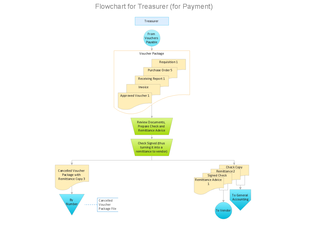
Why Flowchart Important to Accounting Information System?
SSADM Diagram

Data Flow Diagram

Flowchart Definition

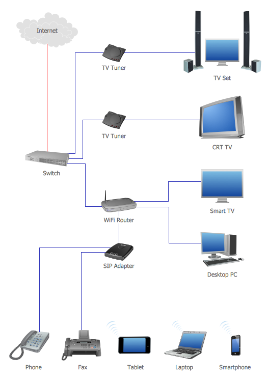
Network Topology Graphical Examples
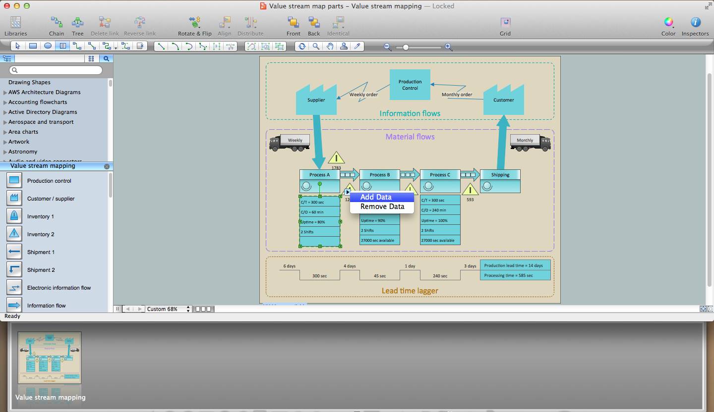
Lean Six Sigma Diagram Software
Fishbone Diagram Problem Solving

Context Diagram Template

This template shows the Context Diagram. It was created in ConceptDraw DIAGRAM diagramming and vector drawing software using the Block Diagrams Solution from the “Diagrams” area of ConceptDraw Solution Park. The context diagram graphically identifies the system. external factors, and relations between them. It’s a high level view of the system. The context diagrams are widely used in software engineering and systems engineering for designing the systems that process the information.
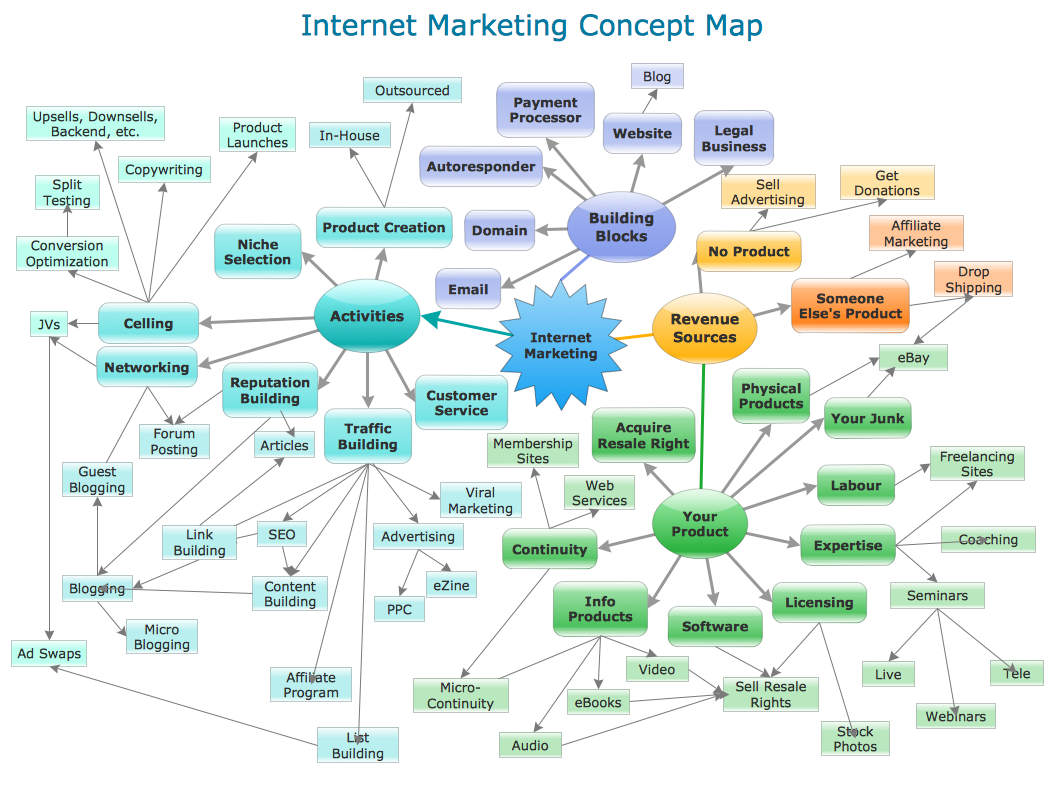
Concept Maps
- Why Is Lds The Most Important Of Ssadm
- Most Important Ssadm Tools And Why
- The Most Important Tools Of Ssadm
- Systems development life cycle | SSADM Diagram | Process ...
- Of The Three Ssadm Which Is The Most Important And Easiest
- Of The Ssadm Lds Dfd Elh Which Is The Most Important
- Structured Systems Analysis and Design Method ( SSADM ) with ...
- Structured Systems Analysis and Design Method ( SSADM ) with ...
- Describe Importance Of Flowchart In System Analysis And Design