UML Use Case Diagram Example. Services UML Diagram. ATM system

State Machine Diagram


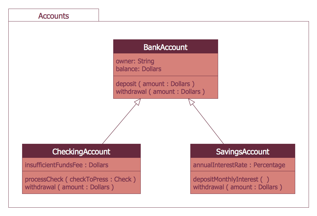
Bank UML Diagram

Bank System
UML Collaboration Diagram. Design Elements

UML Deployment Diagram. Design Elements

UML Activity Diagram

UML Deployment Diagram
Network Topologies


Software Diagram Examples and Templates

UML Component for Bank

UML Sequence Diagram

Finite State Machine

UML Component Diagram

UML Use Case Diagram. Design Elements

- Bank UML Diagram | State Machine Diagram | How to Create a ...
- State Machine Diagram | ATM UML Diagrams | UML Use Case ...
- How to Create a Bank ATM Use Case Diagram | UML Activity ...
- UML Deployment Diagram Example - ATM System UML diagrams ...
- State Machine Diagram | UML Use Case Diagram Example ...
- State Machine Diagram | ATM UML Diagrams | UML Diagram ...
- UML activity diagram - Cash withdrawal from ATM | UML Activity ...
- UML Collaboration Diagram . Design Elements | ATM UML Diagrams ...
- ATM Solutions | ATM UML Diagrams | Bank System | Atm Machine ...
- Uml Class Diagram For Bank Atm
- Class Diagram For Atm Machine
- I Need An Atm Machine Diagram And Label
- UML activity diagram - Cash withdrawal from ATM | ATM UML ...
- UML activity diagram - Cash withdrawal from ATM | UML ...
- UML Use Case Diagram Example. Services UML Diagram . ATM ...
- To Understand The Concept Of Atm And Draw The Object Diagram
- Electrical Diagram Of A Atm Machine
- State Machine Diagram | UML Use Case Diagram Example ...
- Er Diagram For Atm Machine
- Activity Diagram On Bank Atm Machine For Withdrawing Cash