Mechanical Drawing Symbols

 Mechanical Engineering
This solution extends ConceptDraw DIAGRAM.9 mechanical drawing software (or later) with samples of mechanical drawing symbols, templates and libraries of design elements, for help when drafting mechanical engineering drawings, or parts, assembly, pneumatic,
Electrical Symbols — Rotating Equipment

Technical Drawing Software

Electrical Symbols — Qualifying

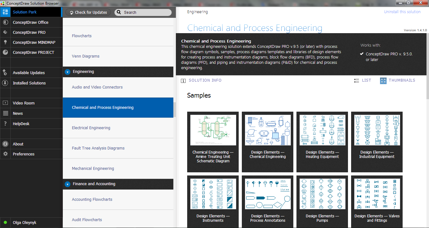
Process Flow Diagram Symbols
Electrical Symbols — Composite Assemblies

Piping and Instrumentation Diagram Software

The vector stencils library "Fluid power equipment" contains 113 symbols of hydraulic and pneumatic equipment including pumps, motors, air compressors, cylinders, meters, gauges, and actuators. Use it to design fluid power and hydraulic control systems.
"Fluid power is the use of fluids under pressure to generate, control, and transmit power. Fluid power is subdivided into hydraulics using a liquid such as mineral oil or water, and pneumatics using a gas such as air or other gases. Compressed-air and water-pressure systems were once used to transmit power from a central source to industrial users over extended geographic areas; fluid power systems today are usually within a single building or mobile machine." [Fluid power. Wikipedia]
The shapes example "Design elements - Fluid power equipment" was created using the ConceptDraw PRO diagramming and vector drawing software extended with the Mechanical Engineering solution from the Engineering area of ConceptDraw Solution Park.
Fluid power symbols

Interior Design Piping Plan - Design Elements

- Engineering | Hydraulic Machine Manufacturer Process Flow Chart
- Hydraulic Press Machine Diagram
- Wiring Diagram Of Hydraulic Compressor Machine
- Electrical Wiring Diagram For A Hydraulic Block Making Machine
- Hydraulic Symbol Stencil
- Mechanical Drawing Symbols | Process Flow Diagram Symbols ...
- Hydraulic schematic | Hydraulic circuits | Hydraulic 5-ported 3 ...
- Flow Chart Of Hydraulic Cylinder Manufacturing
- Mechanical Drawing Symbols | Hydraulic Press Flow Diagram
- Hydraulic Symbol Image