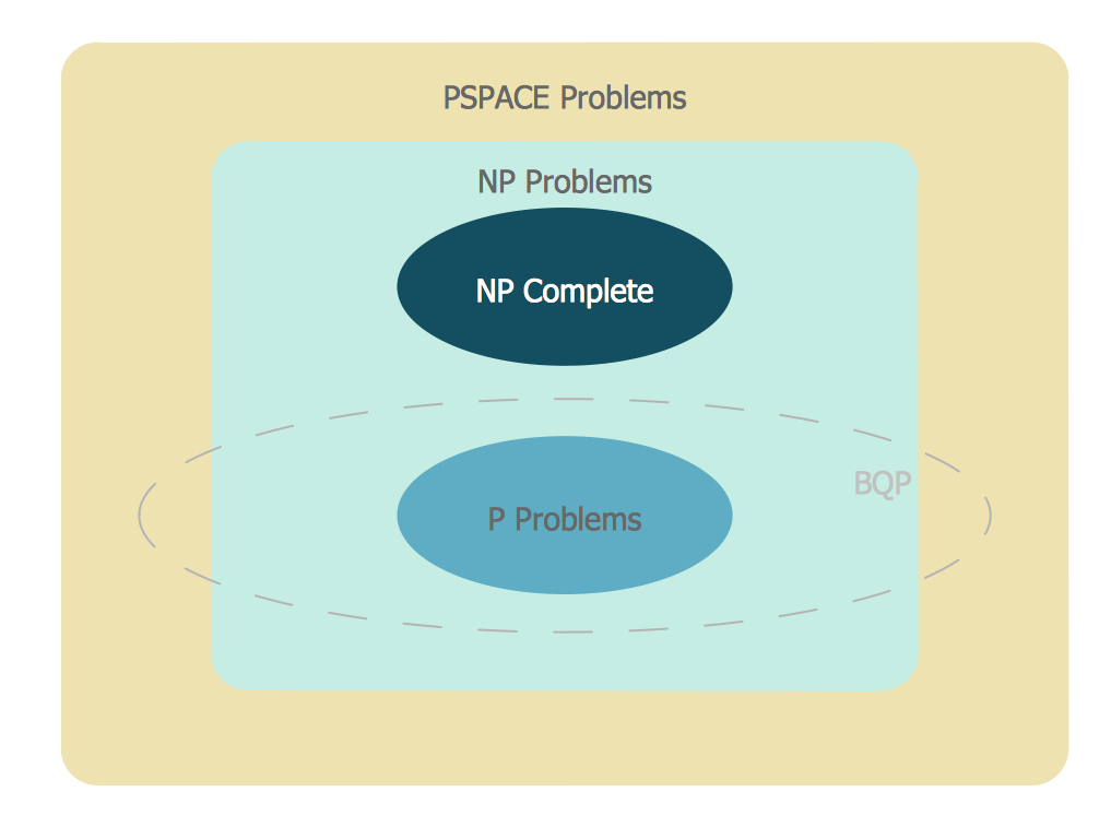
Venn Diagram Examples for Problem Solving
 Word Exchange
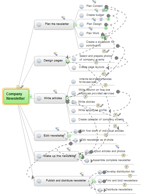
This solution extends ConceptDraw MINDMAP software with the ability to quickly create the framework for a future article or book, fill the structure with ideas, and use it to produce an MS Word document with just a simple click of the mouse.
 Management
This solution extends ConceptDraw DIAGRAM and ConceptDraw MINDMAP with Management Diagrams and Mind Maps (decision making, scheduling, thinking ideas, problem solving, business planning, company organizing, SWOT analysis, preparing and holding meetings
Emergency Plan


 Note Exchange
This solution extends ConceptDraw MINDMAP software with the ability to exchange with Evernote, and access mind maps anywhere, on any computer or mobile device via Evernote.
IDEF0 standard with ConceptDraw DIAGRAM

Entity-Relationship Diagram (ERD) with ConceptDraw DIAGRAM


Think and act effectively
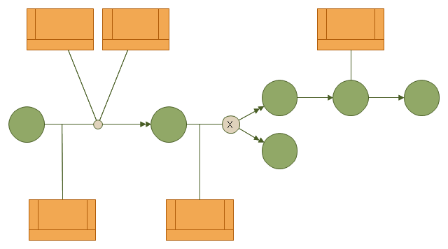
This IDEF3 diagram example was redesigned from the Wikimedia Commons file: 6-4 Example IDEF3 Object State Transition Schematic.jpg.
[commons.wikimedia.org/ wiki/ File:6-4_ Example_ IDEF3_ Object_ State_ Transition_ Schematic.jpg]
"Quick Reading of IDEF3 Process Descriptions: An Example.
An example approach for reading a schematic is described in the following steps. This outline for reading a schematic would be repeated, with few modifications, for all decompositions, whether found in a Process Schematic or an Object Schematic. In general, decompositions are read after the parent schematic has been read and understood.
The Big Picture.
A crucial step in the description-reading process is to understand the big picture
relevant to the real-life situation described. This big picture can be gained by reading and understanding the statement of purpose, statement of scope, objective of the scenario being described, and viewpoint of the IDEF3 Process Description. ...
Scan the Schematic.
Readers should become familiar with the scenario by scanning the schematic from left to right. This involves becoming familiar with the individual elements (e.g., UOBs, links, and junctions) displayed in the schematic. This is not an in-depth study of the schematic; rather, it provides readers with a general impression of the process being described and an overall understanding of the logic flow in the scenario.
Understand the Description.
In this step, readers gain a detailed understanding of the schematic associated with a scenario, object, or a decomposition of a schematic element. This is the part of the communication process that is most individualized and requires the most time. It is helpful to partition the schematic into understandable pieces." [IDEF3 Process Description Capture Method Report AL-TR-1995-XXXX. idef.com/ pdf/ Idef3_ fn.pdf]
The diagram sample "IDEF3 object state transition schematic" was created using the ConceptDraw PRO diagramming and vector drawing software extended with the solution "IDEF Business Process Diagrams" from the area "Business Processes" of ConceptDraw Solution Park.
IDEF3 business process diagram
The vector stencils library "Computer network" contains 51 symbols of computer network devices and equipment for drawing computer network diagrams.
"Network Mapping Software.
A number of software tools exist to design computer network diagrams / or generate visual maps of networks, servers, storage, services, data centers, and other peripherals. Broadly, there are two types of software tools - those that help create diagrams manually and those that generate them using automated / semi-automated approaches.
Type of Software.
(1) Manual - allows users to design and draw logical and physical topology diagrams by manually placing icons and connections.
(2) Automated - generate topology diagrams / maps by traversing the network and automatically discovering resident devices or by importing network data." [Comparison of network diagram software. Wikipedia]
ConceptDraw PRO is the software for manual design of computer network diagrams. The solutions of the Computer and Networks area in ConceptDraw Solution Park extend ConceptDraw PRO with vector stencils libraries, templates and examples for creating the computer network diagrams.
The symbols example "Computer network - Vector stencils library" was created using the ConceptDraw PRO diagramming and vector drawing software extended with the Computer and Networks solution from the Computer and Networks area of ConceptDraw Solution Park.
www.conceptdraw.com/ solution-park/ computer-and-networks
Laptop

Desktop computer

Firewall

Bus

Ethernet

Star network

FDDI Ring

Token-ring

Comm-link

Modem

Laser printer

Inkjet printer

Image scanner

City

Ethernet hub

Wireless router

Network switch

iPod Classic

iPhone/ iPod Touch

Xserve RAID

XServe

Apple Thunderbolt Display

Data store

Mac Pro

iMac

RAID

Mainframe

Rack-mountable server

Server

PDA

Cloud

Computer monitor

Workstation

Router

IP Phone

Fax

Mobile phone

Smartphone

Compact Disk

Mouse

Apple Wireless Mouse

Computer keyboard

Apple Keyboard

Radio tower

Satellite dish

Satellite

Webcam

AirPort Extreme

Airport Express

MacBook

iPhone 4

The vector stencils library "Media" contains 42 digital media icons.
Use it to design your audio, video and multimedia illustrations, presentations, web pages and infographics with ConceptDraw PRO diagramming and vector drawing software.
The vector stencils library "Media" is included in the Audio, Video, Media solution from the Illustration area of ConceptDraw Solution Park.
Multimedia

HD

DVD

Dolby

Pull down screen

DVD ROM

DVD video

DVD disk

DVD

CD

Compact disk 1

Compact disk 2

CD box

CD

Floppy

USB flash drive

USB drive

Flash drive

SIM card

Memory card

Micro SD card

Hard drive

E-book

Flashlight

Game device

CD drive 1

CD drive 2

CD player

MP4 player

Media player 1

Media player 2

Media player 3

Refresh

Stop

Play

Pause

Back

Forward

Money

People

People communication

Communication

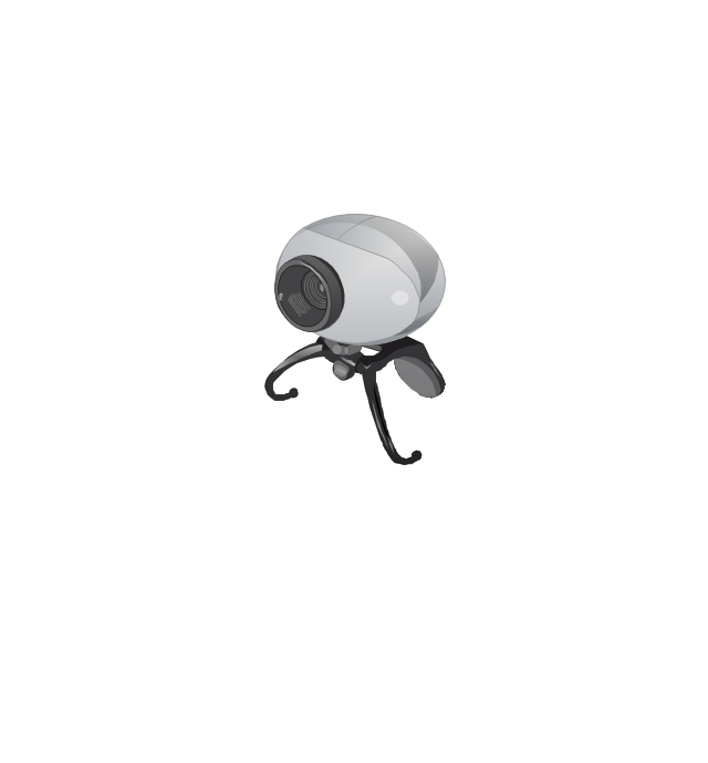
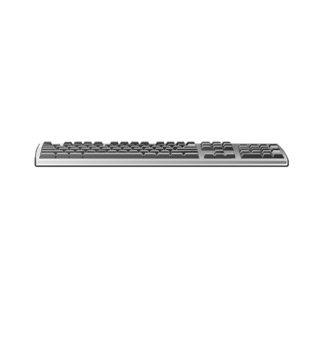
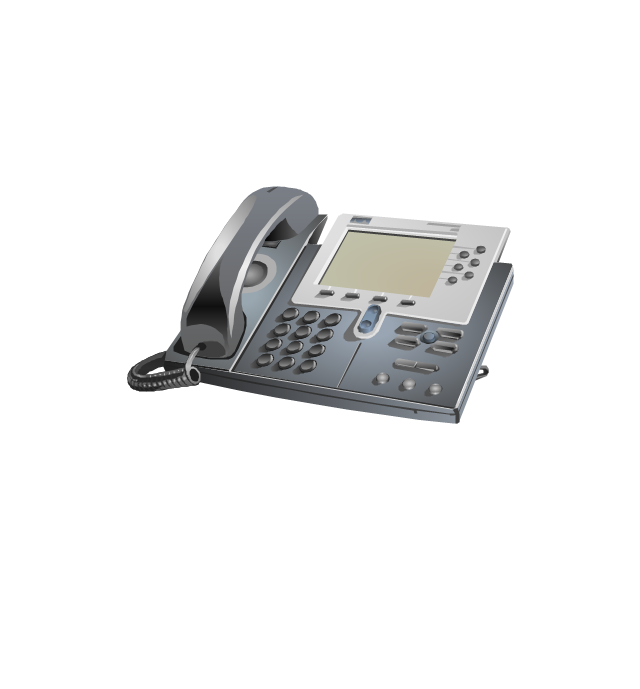
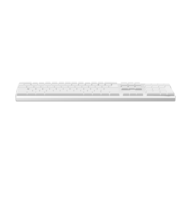
The vector stencils library "Computer peripheral devices" contains 18 clipart images of computer peripheral devices and equipment for drawing network diagrams.
"A peripheral is a device that is connected to a host computer, but not an integral part of it. It expands the host's capabilities but does not form part of the core computer architecture. It is often, but not always, partially or completely dependent on the host.
There are three different types of peripherals:
(1) Input, used to interact with, or send data to the computer (mouse, keyboards, etc.).
(2) Output, which provides output to the user from the computer (monitors, printers, etc.).
(3) Storage, which stores data processed by the computer (hard drives, flash drives, etc.)" [Peripheral. Wikipedia]
The clip art example "Computer peripheral devices - Vector stencils library" was created using the ConceptDraw PRO diagramming and vector drawing software extended with the Computer and Networks solution from the Computer and Networks area of ConceptDraw Solution Park.
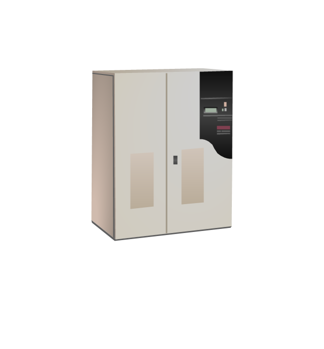
Uninterruptible power supply
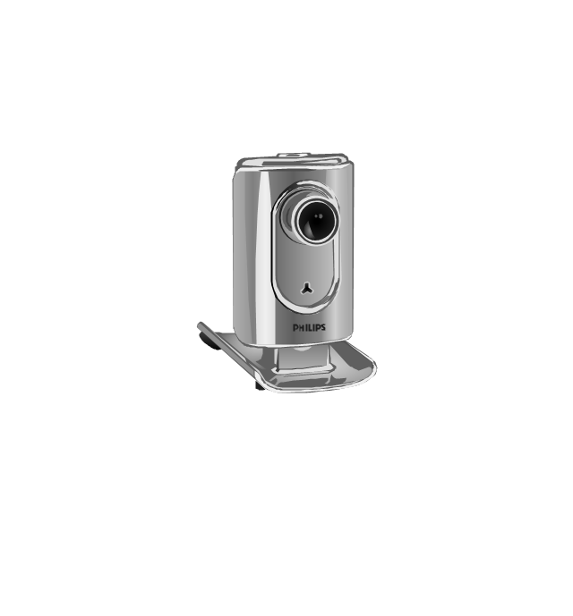
Webcam
Keyboard
Optical mouse

Computer speakers

Headphones

VoIP phone
Apple Keyboard
Apple Mouse

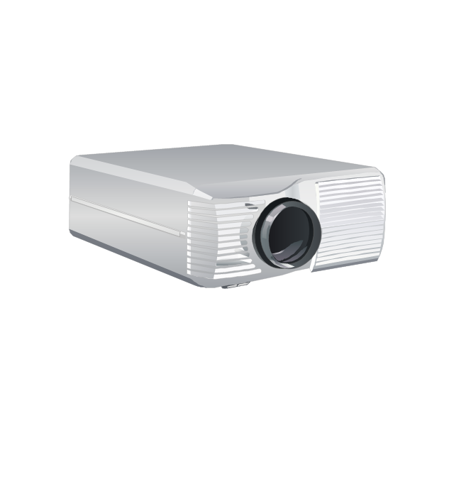
LCD projector
Port adapter
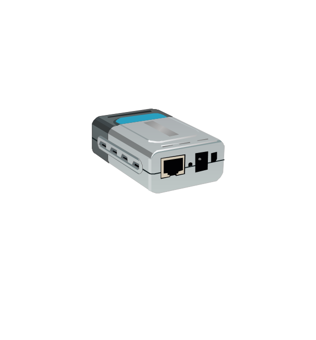
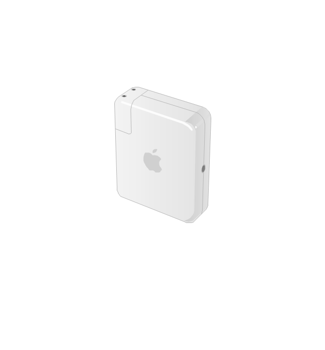
Airport Express
Joystick

Webcam
Video projector
The vector stencils library "AWS Database" contains 30 Amazon Web Services database icons: Amazon DynamoDB symbols, Amazon Relational Database Service symbols, Amazon ElasticCache symbols, Amazon SimpleDB symbols, Amazon Redshift symbols.
Use it to draw AWS architecture diagrams of your cloud service.
The symbols example "AWS Database - Vector stencils library" was created using the ConceptDraw PRO diagramming and vector drawing software extended with the AWS Architecture Diagrams solution from the Computer and Networks area of ConceptDraw Solution Park.
DynamoDB

Table

Item

Items

Attribute

Attributes

Global secondary index

Amazon RDS

RDS DB instance

RDS DB instance standby (Multi-AZ)
-aws-database---vector-stencils-library.png--diagram-flowchart-example.png)
RDS DB instance read replica

MySQL DB instance

Oracle DB instance

MS SQL
instance

PostgreSQL instance

SQL master

SQL slave

PIOP

ElastiCache

Cache node

Redis

Memcached

Amazon SimpleDB

Domain

Amazon Redshift

Solid state disks

DW2 Dense Compute

DW1 Dense Compute

- Design elements - ERD (crow's foot notation) | Entity Relationship ...
- Express-G Diagram | Design elements - Education maps (G-20 ...
- Design elements - VHF UHF SHF | Electrical Engineering | Design ...
- HR symbols - Vector stencils library | Value stream mapping - Vector ...
- Marketing Diagrams | Marketing | Marketing and Sales Organization ...
- Cubicles and work surfaces - Vector stencils library | Rack diagrams ...
- Flowchart design. Flowchart symbols, shapes, stencils and icons ...
- Conceptdraw.com: Mind Map Software, Drawing Tools | Project ...
- Blow-through unit ventilator - HVAC plan | Reflected ceiling plan ...
- Plant Layout Plans | Factory layout floor plan | ConceptDraw ...
- How To Draw Building Plans | How To Create Restaurant Floor Plan ...
- Plumbing and Piping Plans | ConceptDraw Solution Park ...
- RDS DB Instance Read Replica
- Plumbing and Piping Plans | Building Drawing Design Element ...
- Swim Lane Diagrams | Cross-Functional Flowchart (Swim Lanes ...
- Ice Hockey Diagram – Defensive Strategy – Neutral Zone Trap ...
- UML Class Diagram Example - Apartment Plan | Create Floor Plans ...
- Cable TV - Vector stencils library
- Office furniture - Vector stencils library | Building Drawing Software ...
- Local Area Network Figure