Flowchart Components

Electrical Symbols, Electrical Diagram Symbols

Electrical Drawing Software and Electrical Symbols

Components of ER Diagram

Electrical Symbols — Logic Gate Diagram

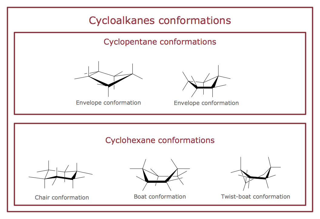
Chemistry Drawings
Metropolitan area networks (MAN). Computer and Network Examples
. Computer and Network Examples")

Interior Design. Plumbing — Design Elements

BPMN 2.0
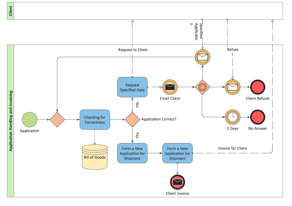
 Business Process Diagrams
Business Process Diagrams solution extends the ConceptDraw DIAGRAM BPM software with RapidDraw interface, templates, samples and numerous libraries based on the BPMN 1.2 and BPMN 2.0 standards, which give you the possibility to visualize equally easy simple and complex processes, to design business models, to quickly develop and document in details any business processes on the stages of project’s planning and implementation.
- How To Draw A Compound Bar Graph And A Histogram
- Carbonyl compound halogenation mechanism | How to Diagram ...
- How to Draw Chemistry Structures | How to Draw a Chemical ...
- Compound Bar Chart And Conponent Bar Chart
- Site layout plan | Building Drawing Software for Design Site Plan ...
- Chemistry Drawings | Chemistry Drawing Software | Chemistry ...
- Building Drawing Software for Design School Layout | Building ...
- Local area network (LAN). Computer and Network Examples ...
- How to Draw Chemistry Structures | Chemistry | Conformations ...
- How to Draw Chemistry Structures | Chemistry | Chemistry Drawing ...