Mechanical Drawing Symbols

Mathematics Symbols

The vector stencils library "Dimensioning and tolerancing" contains 45 symbols of geometric dimensions and mechanical tolerances, geometric symbols, callouts, and text boxes and inserts.
Use these geometric dimensioning and tolerancing (GD&T) shapes to create annotated mechanical drawings.
"Geometric dimensioning and tolerancing (GD&T) is a system for defining and communicating engineering tolerances. It uses a symbolic language on engineering drawings and computer-generated three-dimensional solid models that explicitly describes nominal geometry and its allowable variation. It tells the manufacturing staff and machines what degree of accuracy and precision is needed on each controlled feature of the part. GD&T is used to define the nominal (theoretically perfect) geometry of parts and assemblies, to define the allowable variation in form and possible size of individual features, and to define the allowable variation between features." [Geometric dimensioning and tolerancing. Wikipedia]
The shapes example "Design elements - Dimensioning and tolerancing" was created using the ConceptDraw PRO diagramming and vector drawing software extended with the Mechanical Engineering solution from the ConceptDraw Solution Park.
Dimensioning and tolerancing symbols

The vector stencils library "Dimensioning and tolerancing" contains 45 symbols of geometric dimensions and mechanical tolerances, geometric symbols, callouts, and text boxes and inserts.
Use these geometric dimensioning and tolerancing (GD&T) shapes to create annotated mechanical drawings in the ConceptDraw PRO diagramming and vector drawing software extended with the Mechanical Engineering solution from the Engineering area of ConceptDraw Solution Park.
www.conceptdraw.com/ solution-park/ engineering-mechanical
Datum (old)
-dimensioning-and-tolerancing---vector-stencils-library.png--diagram-flowchart-example.png)
Box callout

Datum symbol

Callout

All around callout

Text block

2 datum frame

Simple frame

Basic frame

1 datum frame

3 datum frame

Straightness

Flatness

Line profile

Circularity

Cylindricity

Surface profile

Position

Concentricity

Symmetry

Parallelism

Perpendicularity

Angularity

Material condition

Arc length

Diameter

Counterbore/ spotface

Countersink

Depth

Slope

Conical taper

Statistical tolerance

Datum (new)
-dimensioning-and-tolerancing---vector-stencils-library.png--diagram-flowchart-example.png)
Datum (new) 2
-2-dimensioning-and-tolerancing---vector-stencils-library.png--diagram-flowchart-example.png)
Target point

Target line

Target area (circle)
-dimensioning-and-tolerancing---vector-stencils-library.png--diagram-flowchart-example.png)
Target area (rectangle)
-dimensioning-and-tolerancing---vector-stencils-library.png--diagram-flowchart-example.png)
Total runout

Total runout 2

Circular runout

Circular runout 2

Surface finish

Surface finish, removal process

Surface finish, no process permitted

 Mechanical Engineering
This solution extends ConceptDraw DIAGRAM.9 mechanical drawing software (or later) with samples of mechanical drawing symbols, templates and libraries of design elements, for help when drafting mechanical engineering drawings, or parts, assembly, pneumatic,
ERD Symbols and Meanings


HelpDesk
How to Draw Geometric Shapes

Technical Flow Chart

 Mathematics
Mathematics solution extends ConceptDraw DIAGRAM software with templates, samples and libraries of vector stencils for drawing the mathematical illustrations, diagrams and charts.
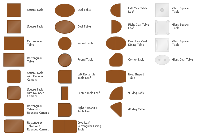
The design elements library Tables contains 27 symbols of tables.
Use the vector stencils library Tables to develop house floor plans, home designs, kitchen and dining room design and furniture layout of cafe or restaurant.
"A table is a form of furniture with a flat horizontal upper surface used to support objects of interest, for storage, show, and/ or manipulation. The surface must be held stable; for reasons of simplicity, this is usually done by support from below by either a column, a "base", or at least three columnar "stands". In special situations, table surfaces may be supported from a nearby wall, or suspended from above.
Common design elements include:
top surfaces of various shapes, including rectangular, rounded, or semi-circular;
legs arranged in two or more similar pairs;
several geometries of folding table that can be collapsed into a smaller volume;
heights ranging up and down from the most common 18–30 inches (46–76 cm) range, often reflecting the height of chairs or bar stools used as seating for people making use of a table, as for eating or performing various manipulations of objects resting on a table;
presence or absence of drawers;
expansion of the surface by insertion of leaves or locking hinged drop leaf sections into horizontal position.
Desks are tables specifically intended for information-manipulation tasks, including writing and use of interactive electronics.
Tables of various shapes, heights, and sizes are designed for specific uses:
Dining room tables are designed to be used for formal dining.
Bedside tables, nightstands, or night tables are small tables used in a bedroom. They are often used for convenient placement of a small lamp, alarm clock, glasses, or other personal items.
Gateleg tables have one or two hinged leaves supported by hinged legs.
Coffee tables are low tables designed for use in a living room, in front of a sofa, for convenient placement of drinks, books, or other personal items.
Refectory tables are long tables designed to seat many people for meals.
Drafting tables usually have a top that can be tilted for making a large or technical drawing. They may also have a ruler or similar element integrated.
Workbenches are sturdy tables, often elevated for use with a high stool or while standing, which are used for assembly, repairs, or other precision handwork.
Nested tables are a set of small tables of graduated size that can be stacked together, each fitting within the one immediately larger. They are for occasional use (such as a tea party), hence the stackable design." [Table (furniture). Wikipedia]
The shapes library Tables is provided by the Floor Plans solution from the Building Plans area of ConceptDraw Solution Park.
The vector stencils library "Welding" contains 38 welding joint symbols to identify fillets, contours, resistance seams, grooves, surfacing, and backing.
Use it to indicate welding operations on working drawings.
"Welding is a fabrication or sculptural process that joins materials, usually metals or thermoplastics, by causing coalescence. This is often done by melting the workpieces and adding a filler material to form a pool of molten material (the weld pool) that cools to become a strong joint, with pressure sometimes used in conjunction with heat, or by itself, to produce the weld. This is in contrast with soldering and brazing, which involve melting a lower-melting-point material between the workpieces to form a bond between them, without melting the workpieces.
Many different energy sources can be used for welding, including a gas flame, an electric arc, a laser, an electron beam, friction, and ultrasound.
Welds can be geometrically prepared in many different ways. The five basic types of weld joints are the butt joint, lap joint, corner joint, edge joint, and T-joint (a variant of this last is the cruciform joint). Other variations exist as well - for example, double-V preparation joints are characterized by the two pieces of material each tapering to a single center point at one-half their height. Single-U and double-U preparation joints are also fairly common - instead of having straight edges like the single-V and double-V preparation joints, they are curved, forming the shape of a U. Lap joints are also commonly more than two pieces thick - depending on the process used and the thickness of the material, many pieces can be welded together in a lap joint geometry." [Welding. Wikipedia]
The shapes example "Design elements - Welding" was created using the ConceptDraw PRO diagramming and vector drawing software extended with the Mechanical Engineering solution from the Engineering area of ConceptDraw Solution Park.
Welding joint symbols

Interior Design. Storage and Distribution — Design Elements

Network Glossary Definition


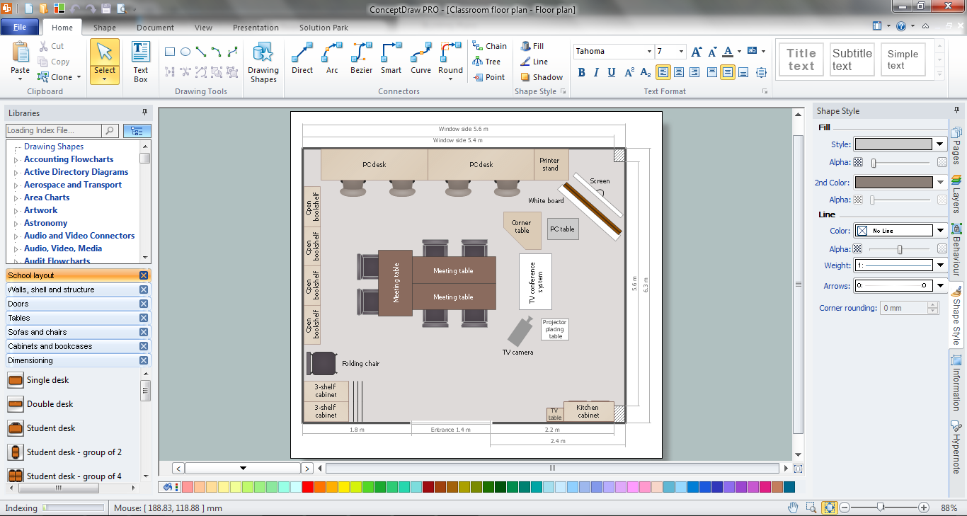
Classroom Seating Chart Maker
- Mechanical Drawing Symbols | Basic Flowchart Symbols and ...
- Basic Flowchart Symbols and Meaning | Mechanical Drawing ...
- Mechanical Drawing Symbols | ERD Symbols and Meanings ...
- Mathematics Symbols | Mechanical Drawing Symbols | Scientific ...
- Mechanical Drawing Symbols | Process Flow Diagram Symbols ...
- Geometric Symbols In Machine Drawing
- Mechanical Drawing Symbols | Design elements - Dimensioning ...
- Mechanical Drawing Symbols | Mathematics Symbols | Scientific ...
- Mechanical Drawing Symbols | Mathematics Symbols | How to Draw ...
- Mechanical Drawing Symbols | Mathematics Symbols | Design ...
- Mechanical Drawing Symbols | Design elements - Dimensioning ...
- Mechanical Drawing Symbols | Geometric Symbol And Machining ...
- Mechanical Drawing Symbols | Geometric Dimensions And ...
- Scientific Symbols Chart | Mechanical Drawing Symbols | How to ...
- Mechanical Drawing Symbols | Electrical Symbols , Electrical ...
- Basic Flowchart Symbols and Meaning | Mechanical Drawing ...
- Geometric Symbols In Engineering Drawing
- Mathematics Symbols | Mechanical Drawing Symbols | Design ...
- Geometry Drawing And Symbols
- Geometric Box Design