COM and OLE Diagram

Influence Diagram Software
SDL Diagram
Gane Sarson Diagram

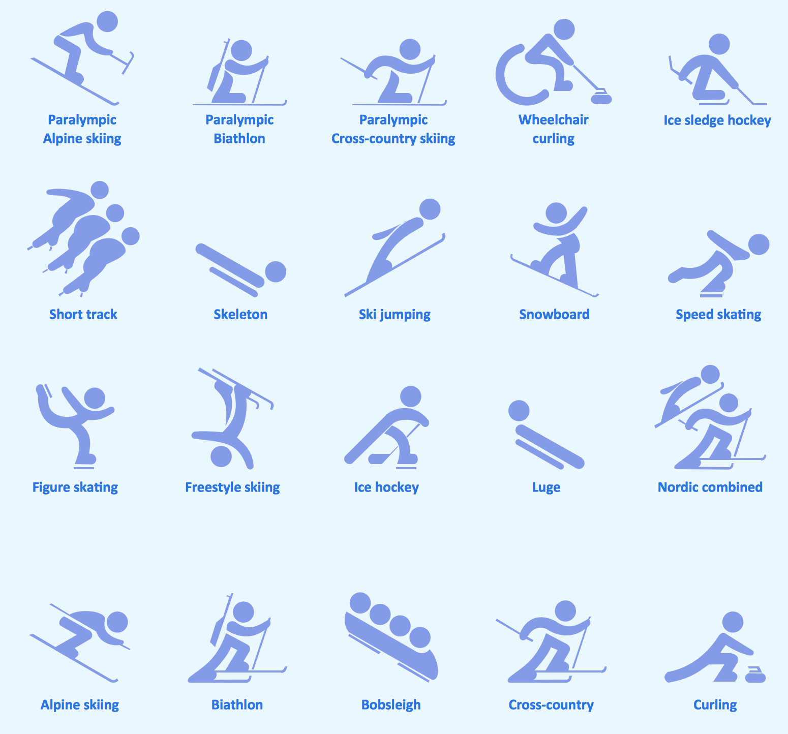
Sport pictograms. Olympic Games
HelpDesk
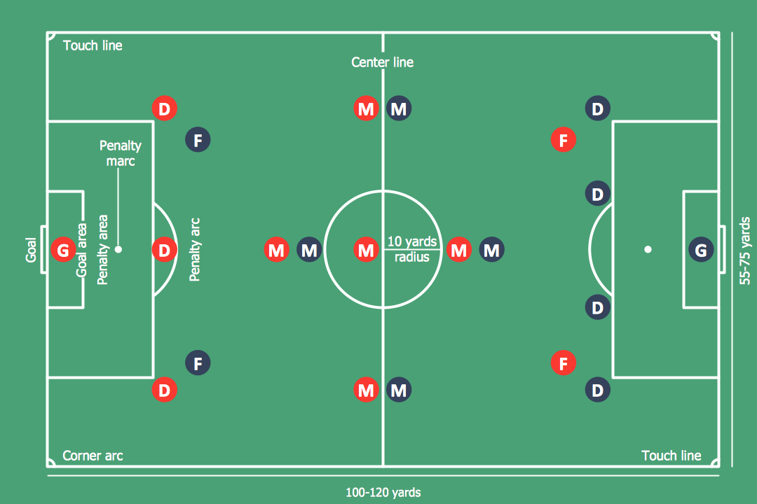
How to Make Soccer Position Diagram
Basketball Illustrations

Entity Relationship Diagram - ERD - Software for Design Crows Foot ER Diagrams
_Win_Mac.png)

Network Diagram Software. LAN Network Diagrams. Physical Office Network Diagrams


Technical Flow Chart Example

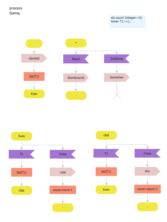
 Specification and Description Language (SDL)
For people in the field of systems engineering or system design, working with specification and description language (sdl) and finite state machines (fsm).
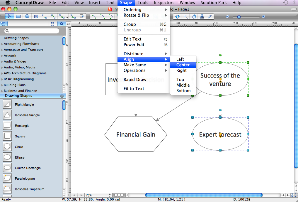
Technical Drawing Software

Influence Diagram

Spatial infographics Design Elements: Transport Map
Electrical Diagram Software


- Top 5 Android Flow Chart Apps | Technical Flow Chart | Online Flow ...
- Technical Diagram Of Av Solution
- Er Diagram Of Game
- Entity Relationship Diagram For Online Multi Player Game
- Diagram Overview Game
- Entity Relationship Diagram Racing Game
- Game Entity Relationship Diagram Sample
- Electrical Symbols, Electrical Diagram Symbols | Basketball Court ...
- Game Context Diagram
- Machine Diagram With Dimension
- Chen's ERD of MMORPG | SDL Diagram | ER Diagram for Cloud ...
- Entity Relationship Diagram For Games
- Game Algorithm Block Diagram
- Game Er Diagram
- Technical Flow Chart | The Best Choice for Creating Diagram ...
- Game Management System Er Diagram Pdf Download
- Design elements - AWS Mobile Services and Game Development ...
- Telecommunication Network Diagrams | Process Flowchart | SDL ...
- Process Flowchart | How to Create an Electrical Diagram Using ...
- Sport Field Plans | Sport pictograms. Olympic Games | Winter Sports ...