The vector stencils library "Electrical and telecom" contains 83 symbols of electrical and telecommunication equipment.
Use these shapes for drawing electrical and telecom system design floor plans, cabling layout schemes, and wiring diagrams in the ConceptDraw PRO diagramming and vector drawing software.
The vector stencils library "Electrical and telecom" is included in the Electric and Telecom Plans solution from the Building Plans area of ConceptDraw Solution Park.
Luminaire ceiling mount

Enclosed ceiling luminaire

Wall light

1-light bar

2-light bar

4-light bar

6-light bar

8-light bar

Down lighter

Outdoor lightning

Outdoor lightning, bollard

Batten fluorescent, 1 lamp

Batten fluorescent, 2 lamps

Batten fluorescent, 3 lamps

Batten fluorescent, 4 lamps

Surface Fluorescent Light

Modular fluorescent fitting

Modular fluorescent fitting, inverter

Modular fluorescent fitting 2

Pull-cord switch

Emergency light

Emergency light 2

Emergency sign

Switch

Switch, 1 pole

Switch, 2 pole

Switch, 2-way

Multi-switch

Switch, intermediate

Dimmer switch

Dimmer switch 2

Socket

Socket 2

Switched socket

Switched socket 2

Double socket

Double socket 2

Socket outlet

Telephone outlet

Telephone outlet 2

Stereo outlet

Television outlet

Service panel, surface

Service panel, inset

Thermostat

Ceiling fan

Hold open unit

Detector

Fire alarm

City Fire Alarm Station

Fire Alarm Station

Fire Alarm Bell

Fire Alarm Central Station

Automatic Fire Alarm Device

Main control

Ground

Doorbell

Push Button

Buzzer

Annunciator

Horn

Maid's Signal Plug

Signal Central Station

Doorbell Chime

Doorbell Transformer

Magnetic Door Hold

Intercom

Telephone Key System

Digital Satellite System

Inside Antenna

Outside Antenna

Electric Motors

Single Phase

Three of Poly Phase

Wall Mounted Electrical Junction Box for Hardware

Wall Mounted Telephone/Data Junction Box for Hardware

Card Reader Access System

Emergency Release Button

Motion Sensor

Electric Door Opener

Watchman's Station

Watchman's Central Station

Battery

Wiring Diagrams with ConceptDraw DIAGRAM

Electrical and Telecom Plan Software

Electrical Symbols, Electrical Diagram Symbols

 Electrical Engineering
This solution extends ConceptDraw DIAGRAM.9.5 (or later) with electrical engineering samples, electrical schematic symbols, electrical diagram symbols, templates and libraries of design elements, to help you design electrical schematics, digital and analog
Electrical Symbols — Power Sources

Electrical Symbols — Electrical Circuits

Electrical Symbols — Thermo

Electrical Diagram Software


The design elements library Building core contains 80 symbols of stairs, elevators, escalators, restroom fixtures, and a safe.
Use the shapes library Building core to draw the structural diagrams, bathroom layouts, building automation, architectural drawings, and riser diagrams, as well as space plans, store and shopping mall plans, and facility planning, plant layouts using the ConceptDraw PRO diagramming and vector drawing software.
"In architecture and building engineering, a floor plan otherwise known as a Scottish plan is a drawing to scale, showing a view from above, of the relationships between rooms, spaces and other physical features at one level of a structure.
The term may be used in general to describe any drawing showing the physical layout of objects.
A floor plan could show:
Interior walls and hallways;
Restrooms;
Windows and doors;
Appliances such as stoves, refrigerators, water heater etc.;
Interior features such as fireplaces, saunas and whirlpools;
The use of all rooms shall be indicated." [Floor plan. Wikipedia]
The vector stencils library Building core is provided by the Floor Plans solution from the Building Plans area of ConceptDraw Solution Park.
 Building Design Package
Architects and building engineers to develop building documentation, floor plans and building blueprints, to help designers depict bright and innovative design solutions, make beautiful design proposals and represent the most daring design ideas, to communicate ideas and concepts that relate to construction and design, explain requirements to a building contractor and builders, record completed work, and make a record of what currently exists.
The vector stencils library "Building core" contains 80 shapes for stairs, elevators, escalators, restroom fixtures, and a safe. Use it for structural diagrams, bathroom layouts, building automation, architectural drawings, and riser diagrams in the ConceptDraw PRO diagramming and vector drawing software extended with the Floor Plans solution from the Building Plans area of ConceptDraw Solution Park.
Ornamental stair
Ornamental stair, break
Ornamental stair, handrails
Ornamental stair, handrails, break
Ornamental stair 2
Ornamental stair 2, handrails
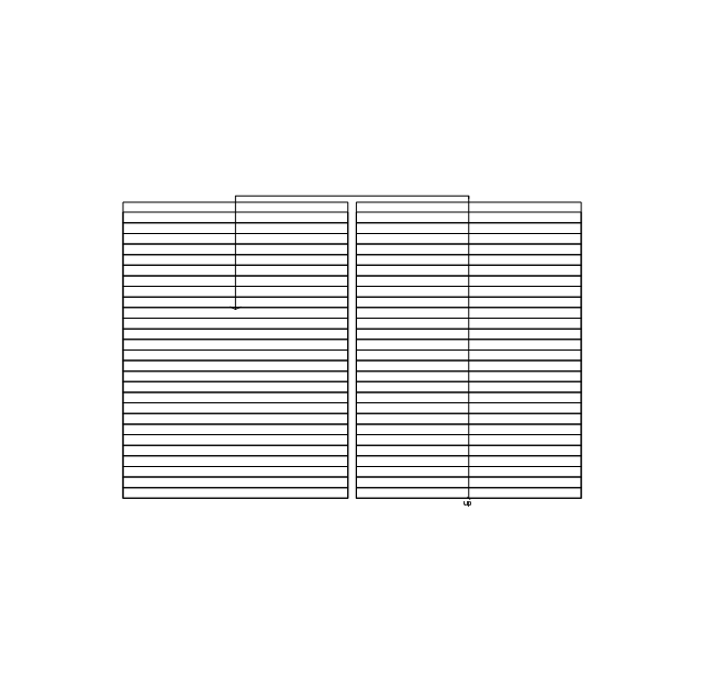
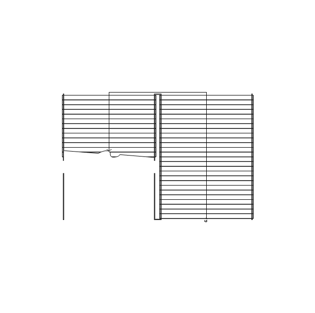
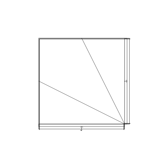
Scissor staircase
Scissor staircase, break
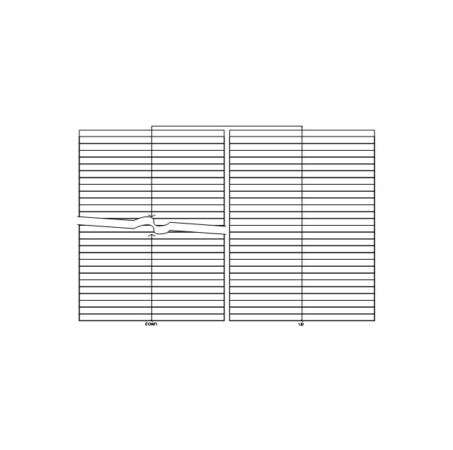
Scissor staircase, break 2
Scissor staircase, handrails
Scissor staircase, handrails, break
Scissor staircase, handrails, break 2
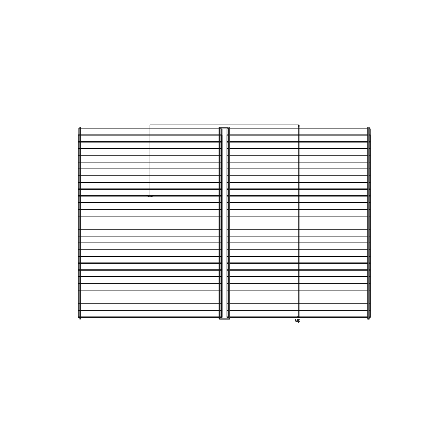
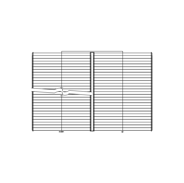
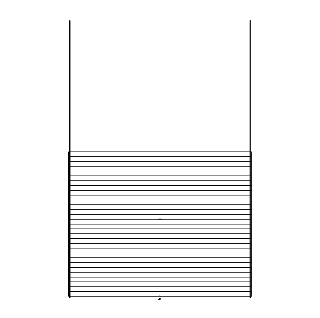
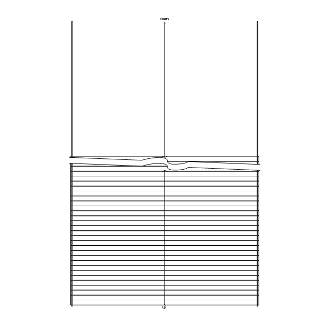
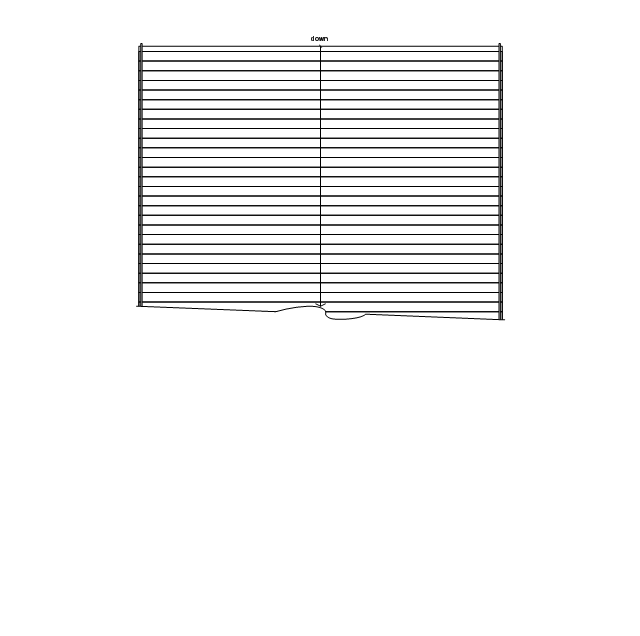
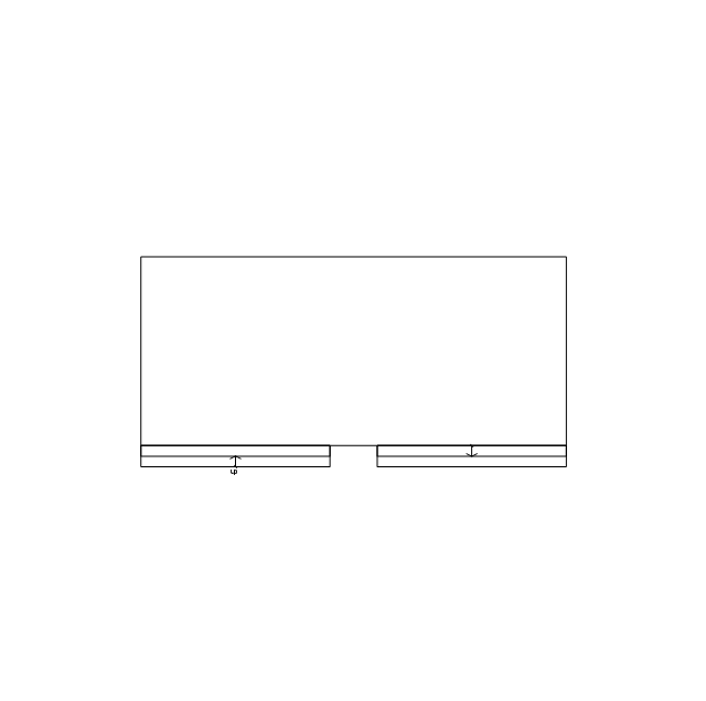
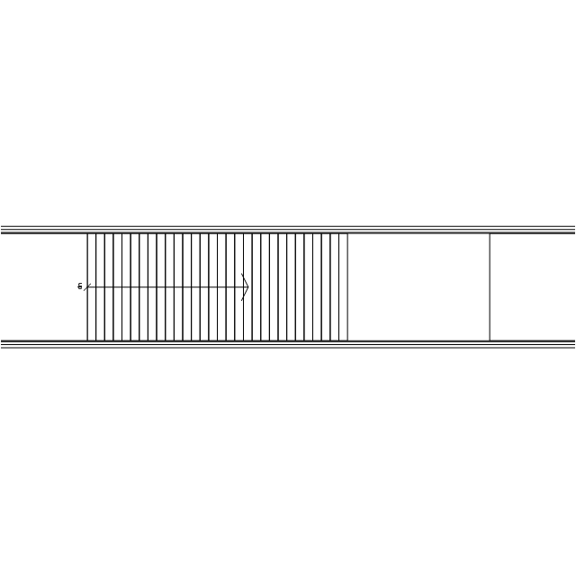
Straight staircase
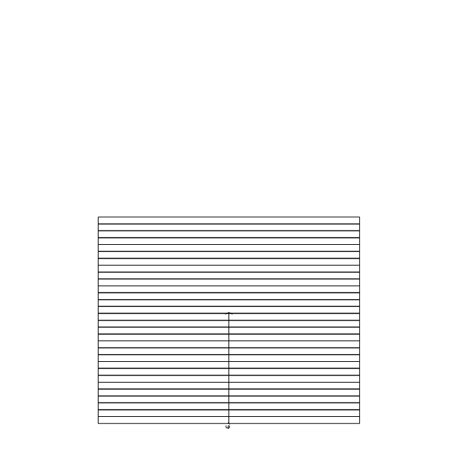
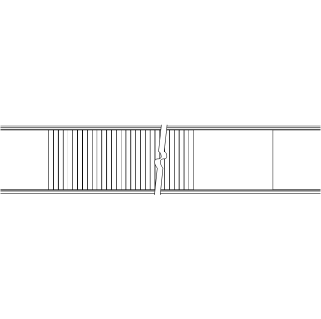
Straight staircase, break
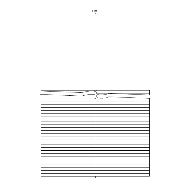
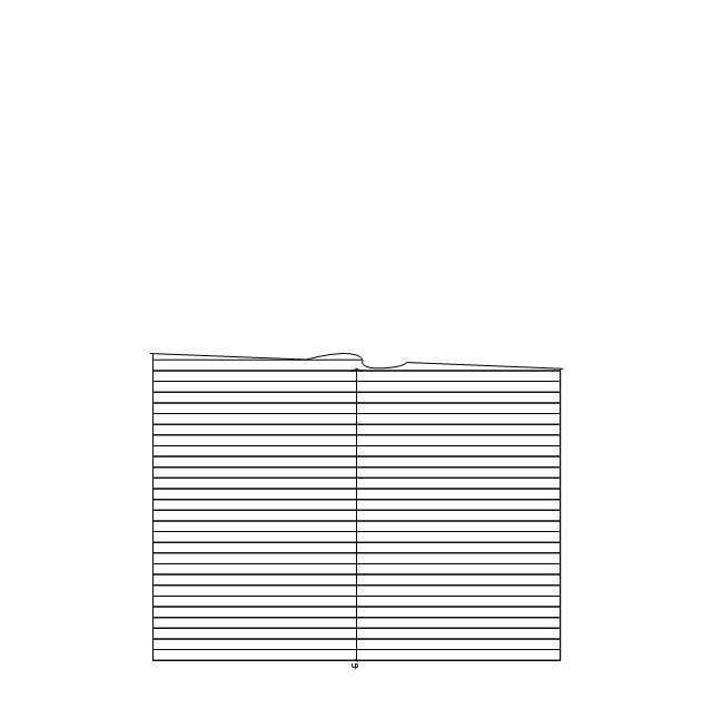
Straight staircase, break, upper
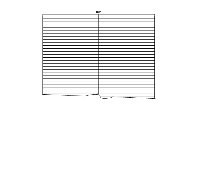
Straight staircase, break, lower
Straight staircase, handrails
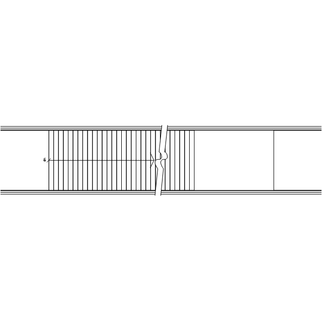
Straight staircase, handrails, break
Straight staircase, handrails, break, upper
Straight staircase, handrails, break, lower
Spiral staircase, ascending
Spiral staircase, descending
Spiral staircase, handrails, ascending
Spiral staircase, handrails, descending

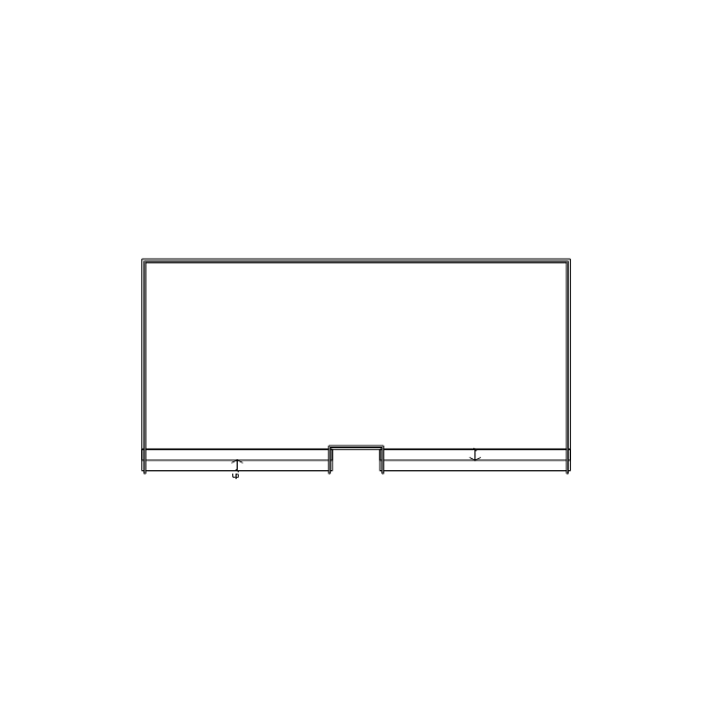
Stair section
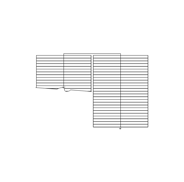
Z-shaped stairs

Z-shaped stairs, handrails
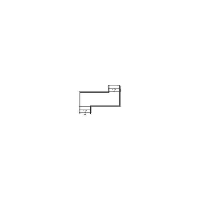
Z-shaped stairs 2
Z-shaped stairs 2, handrails

Straight run stairs
Straight run stairs, handrails
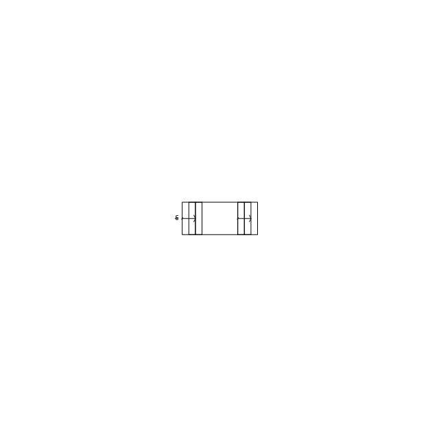
Divided return stairs
Divided return stairs, handrails
Divided return stairs 2
Divided return stairs 2, handrails
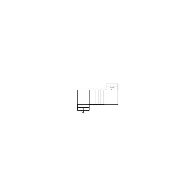
L-shaped stairs
L-shaped stairs, handrails
Stair break
Up direction
Down direction
Stair landing, 0 step

Stair landing, 2 step
Stair landing, 3 step
Stair landing, 0 step, stagger
Stair landing, 2 step, stagger
Stair landing, 3 step, stagger
Corner landing, round, 1 step
Corner landing, round, 2 step
Corner landing, round, 3 step
Corner landing, square, 1 step

Corner landing, square, 2 step

Corner landing, square, 3 step
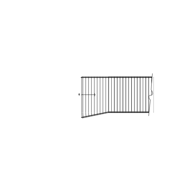
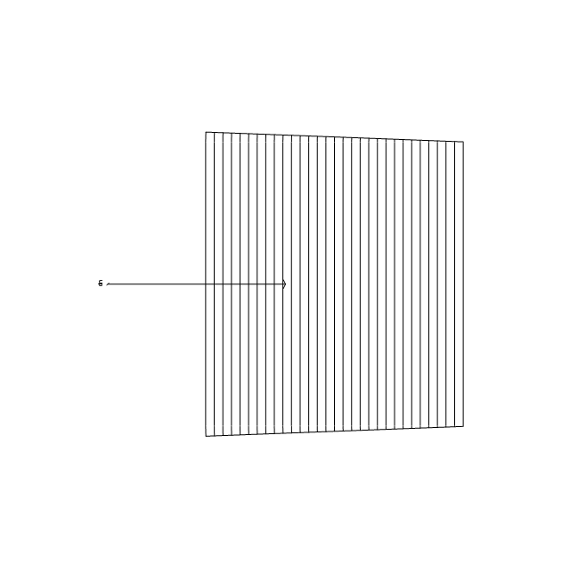
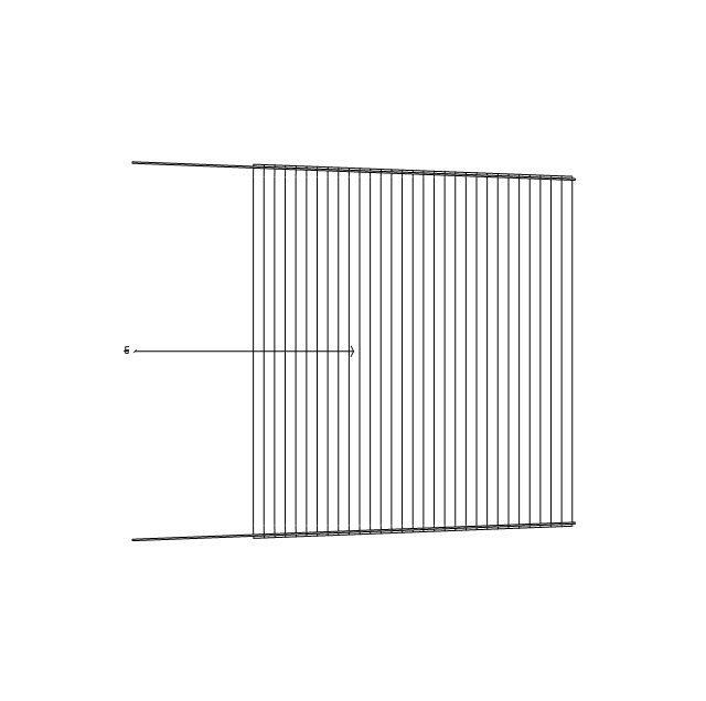
Escalator
Escalator, ascending
Escalator, descending

Escalator, break
Escalator, break, ascending
Escalator, break, descending

Hand rail

Corner hand rail 1
Corner hand rail 2
Toilet
Sink
Urinal
Toilet stall, in, left
Toilet stall, in, right
Toilet stall, out, left

Toilet stall, out, right

Toilet stall 2, in, left
Toilet stall 2, in, right
Toilet stall 2, out, left
Toilet stall 2, out, right

Vault
Elevator

Elevator, rear door

Freight elevator

Freight elevator, rear door
Chute

Washroom counter 1

Washroom counter 2

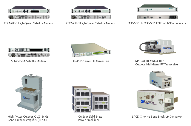
Comtech EF Data Corporation is the vendor of telecommunication solutions for fixed and mobile/ transportable satellite-based applications: Advanced VSAT Solutions, Modems, RAN & WAN Optimization, Managed Bandwidth, RF Products. [comtechefdata.com]
The telecom equipment clipart icons example "Design elements - Comtech" was created using the ConceptDraw PRO diagramming and vector drawing software extended with the Telecommunication Network Diagrams solution from the Computer and Networks area of ConceptDraw Solution Park.
The telecom equipment clipart icons example "Design elements - Comtech" was created using the ConceptDraw PRO diagramming and vector drawing software extended with the Telecommunication Network Diagrams solution from the Computer and Networks area of ConceptDraw Solution Park.
Telecom network equipment
- Electrical Fittings And Accessories With Their Symbol
- Floor Plan Smoke Detector Symbol
- How To use House Electrical Plan Software | Electrical Symbols ...
- Telecom Drawing Symbols Autocad
- Panel Design Symbols
- Electrical Panel Wiring Diagram
- Lighting and switch layout | Design elements - Outlets | Electrical ...
- Drawing And Connection Diagram Of Electrical Control Panel
- Autocad Fire Detection Symbols
- Fire Alarm Bell Electrical Symbol
- Symbol Of A Smoke Detector
- Electrical Symbols , Electrical Diagram Symbols | How To use House ...
- Electrical Symbols , Electrical Diagram Symbols | Design elements ...
- Design elements - Electrical and telecom | Electrical and telecom ...
- Double Socket Outlet Symbol
- Indicator Layout Diagram Symbol
- Process Flow Diagram Symbols
- Symbols Of Electrical Fittings For Floor Plan
- EU greenhouse gas emissions - Management infogram | Design ...
- Wall Light Electrical Symbol