Ice Hockey Rink Dimensions
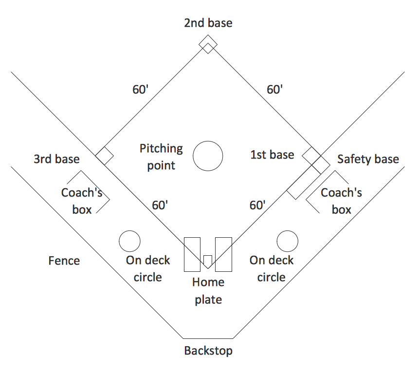
Simple Baseball Field — Sample
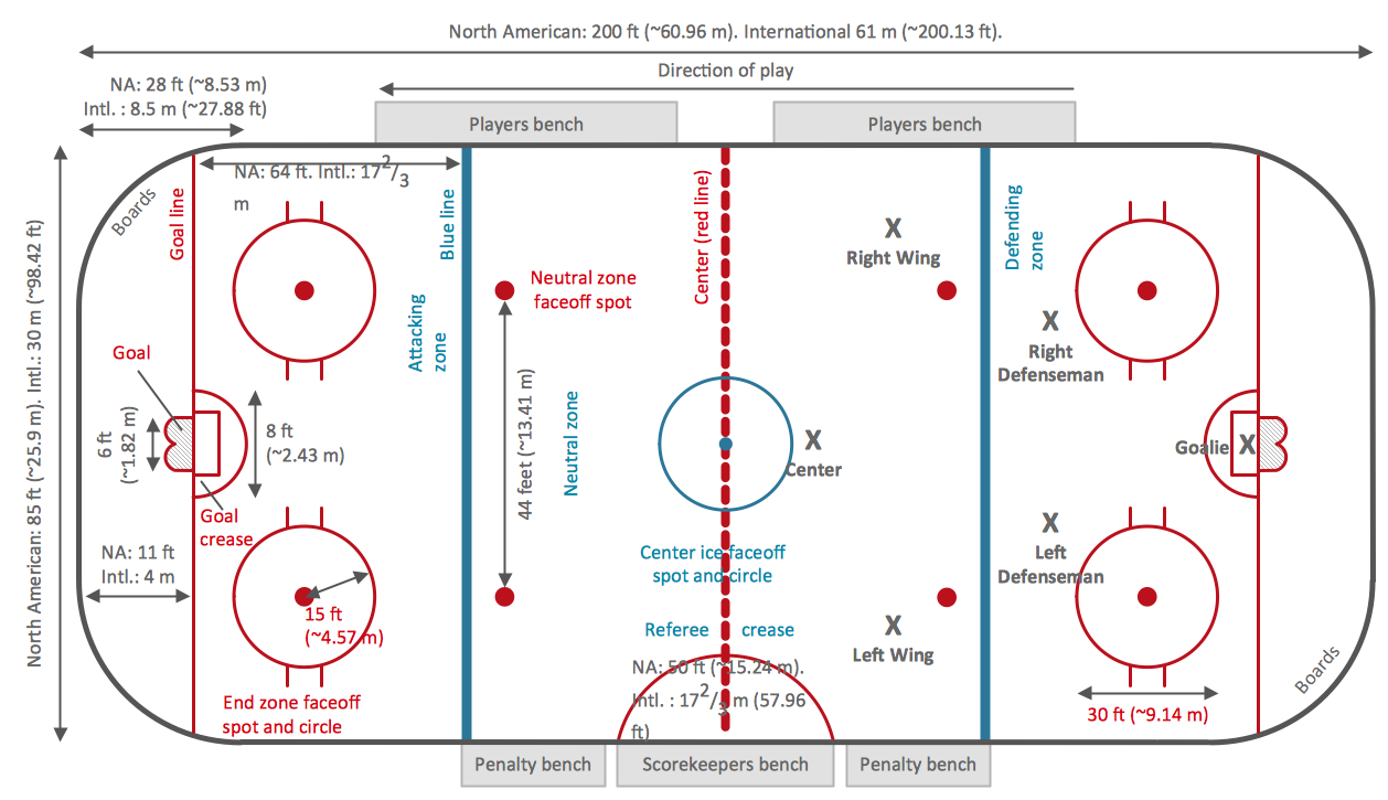
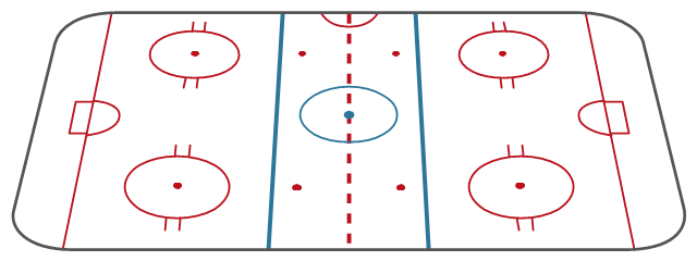
"An ice hockey rink is an ice rink that is specifically designed for ice hockey, a team sport. It is rectangular with rounded corners and surrounded by a wall approximately 1 meter (40-48 inches) high called the boards. ...
There are two standard sizes for hockey rinks: one used primarily in North America, the other used in the rest of the world.
International.
Hockey rinks in most of the world follow the International Ice Hockey Federation (IIHF) specifications, which is 61 metres (200 ft) × 30.5 metres (100 ft) with a corner radius of 8.5 metres (28 ft). The distance from the end boards to the nearest goal line is 4 metres (13 ft). The distance from each goal line to the nearest blue line is 17.3 metres (57 ft). The distance between the two blue lines is also 17.3 metres (57 ft).
North American.
Most North American rinks follow the National Hockey League (NHL) specifications of 200 feet (61 m) × 85 feet (26 m) with a corner radius of 28 feet (8.5 m). The distance from the end boards to the nearest goal line is 11 feet (3.4 m). The NHL attacking zones are expanded, with blue lines 64 feet (20 m) from the goal line and 50 feet (15 m) apart." [Ice hockey rink. Wikipedia]
The diagram template "Hockey rink" for the ConceptDraw PRO diagramming and vector drawing software is included in the Hockey solution from the Sport area of ConceptDraw Solution Park.
Ice hockey rink diagram template

Entity Relationship Diagram - ERD - Software for Design Crows Foot ER Diagrams
_Win_Mac.png)

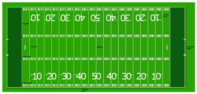
"Football games are played on a rectangular field that measures 120 yards (110 m) long and 53.33 yards (48.76 m) wide. Lines marked along the ends and sides of the field are known respectively as the end lines and side lines, and goal lines are marked 9 yards (8.2 m) outward from each end line. Weighted pylons are placed on the inside corner of the intersections of the goal lines and end lines.
White markings on the field identify the distance from the end zone. Inbound lines, or hash marks, are short parallel lines that mark off 1 yard (0.91 m) increments. Yard lines, which run the width of the field, are marked every 5 yards (4.6 m). A line one yard wide is placed at each end of the field. This line is marked at the center of the two-yard line in professional play and at the three-yard line in college play. Numerals that display the yard lines in multiples of ten are placed along both sides of the field.
Goalposts are at the center of the plane of each of the two end lines. The crossbar of these posts is ten feet (3 meters) above the ground, with vertical uprights at the end of the crossbar 18 feet 6 inches (6 m) apart for professional and collegiate play and 23 feet 4 inches (7 m) apart for high school play. The uprights extend vertically 10 yards on professional fields, a minimum of 10 yards on college fields, and a minimum of ten feet on high school fields. Goal posts are padded at the base, and orange ribbons are normally placed at the tip of each upright." [American football. Wikipedia]
The diagram example "Horizontal colored football field" was created using the ConceptDraw PRO diagramming and vector drawing software extended with the Football solution from the Sport area of ConceptDraw Solution Park.
American football field diagram
"Snowboards are boards that are usually the width of one's foot longways, with the ability to glide on snow. Snowboards are differentiated from monoskis by the stance of the user. In monoskiing, the user stands with feet inline with direction of travel (facing tip of monoski/ downhill) (parallel to long axis of board), whereas in snowboarding, users stand with feet transverse (more or less) to the longitude of the board. Users of such equipment may be referred to as snowboarders. Commercial snowboards generally require extra equipment such as bindings and special boots which help secure both feet of a snowboarder, who generally rides in an upright position. These type of boards are commonly used by people at ski hills or resorts for leisure, entertainment and competitive purposes in the activity called snowboarding." [Snowboard. Wikipedia]
The vector icon example "Snowboard" represents one of 20 symbols from the Winter sports pictograms library for the ConceptDraw PRO diagramming and vector drawing software.
The design elements library Winter sports pictograms is included in the Winter Sports solution from the Sport area of ConceptDraw Solution Park.
Snowboard

HelpDesk
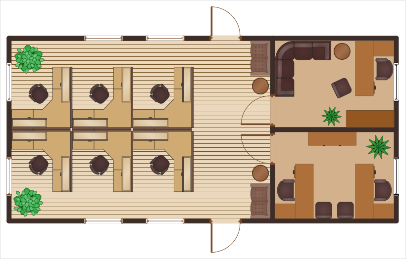
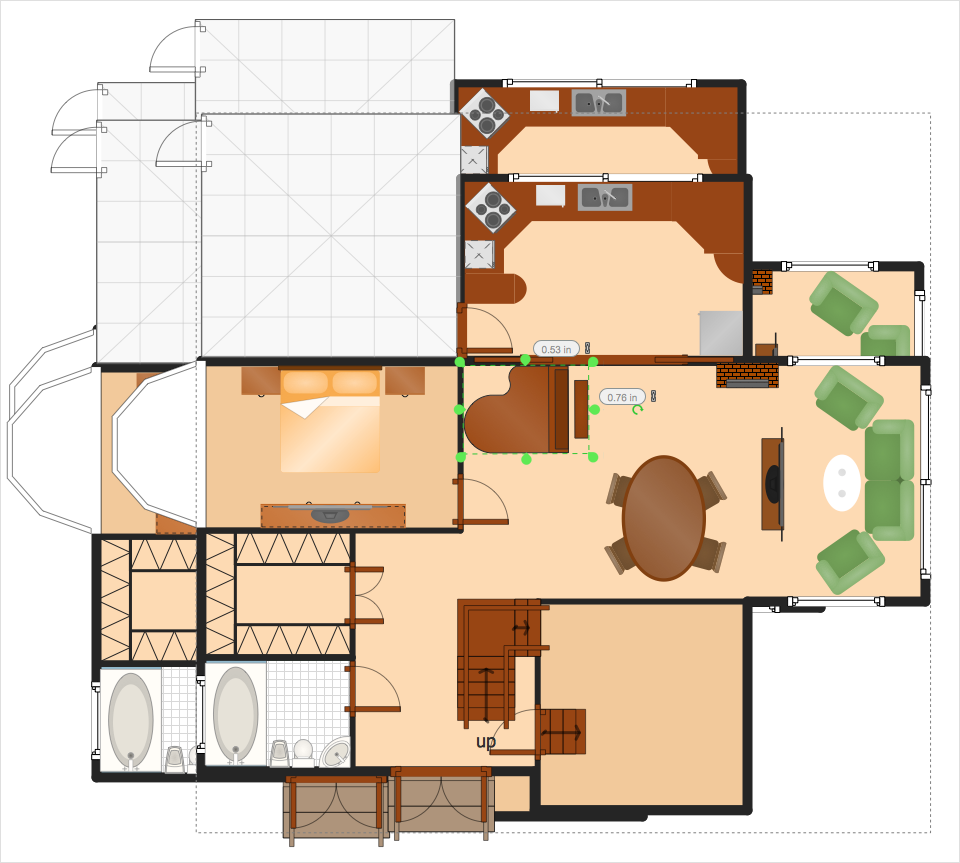
How to Draw a Floor Plan for Your Office
"Markings.
Lines.
The centre line divides the ice in half crosswise. It is used to judge icing, meaning that if a team sends the puck across the centre line (red line), blue line and then across the goal line (that is to say, shoots or dumps the puck past the goal line from behind their own side of the centre line) it is said to be icing. ...
Faceoff spots and circles.
There are 9 faceoff spots on a hockey rink. Most faceoffs take place at these spots. There are two spots in each end zone, two at each end of the neutral zone, and one in the centre of the rink.
There are faceoff circles around the centre ice and end zone faceoff spots. There are hash marks painted on the ice near the end zone faceoff spots. The circles and hash marks show where players may legally position themselves during a faceoff or in game play. ...
Spot and circle dimensions.
Both the center faceoff spot and center faceoff circle are blue. The spot is a solid blue circle 12 inches (30 cm) in diameter. Within the spot is a center, a circle 30 feet (9.1 m) in diameter, painted with a blue line 2 inches (5.1 cm) in width.
All of the other faceoff spots have outlines 2 inches (5.1 cm) thick, forming a circle 2 feet (0.61 m) in diameter measured from the outsides of the outlines, and are filled in with red in all areas except for the 3 inches (7.6 cm) space from the tops and bottoms of the circles, measured from the insides of the outline. ...
Goal posts and nets.
At each end of the ice, there is a goal consisting of a metal goal frame and cloth net in which each team must place the puck to earn points. According to NHL and IIHF rules, the entire puck must cross the entire goal line in order to be counted as a goal. ...
Goal area.
The crease is a special area of the ice designed to allow the goaltender to perform without interference. In most leagues, goals are disallowed if an attacking player enters the goal crease with a stick, skate, or any body part before the puck. For the purposes of this rule, the crease extends vertically from the painted lines to the top of the goal frame. ...
Goaltender trapezoid.
During the 2004-05 American Hockey League (AHL) season, an experimental rule was implemented for the first seven weeks of the season, instituting a goaltender trap zone, more commonly called the trapezoid in reference to its shape. Under the rule, it is prohibited for the goaltender to handle the puck anywhere behind the goal line that is not within the trapezoidal area. If they do so they are assessed a minor penalty for delay of game. ...
Referee's crease.
The referee's crease is a semicircle ten feet in radius in front of the scorekeepers bench." [Ice hockey rink. Wikipedia]
The diagram template "Ice hockey rink view from long side" for the ConceptDraw PRO diagramming and vector drawing software is included in the Hockey solution from the Sport area of ConceptDraw Solution Park.
Ice hockey rink diagram template
HelpDesk
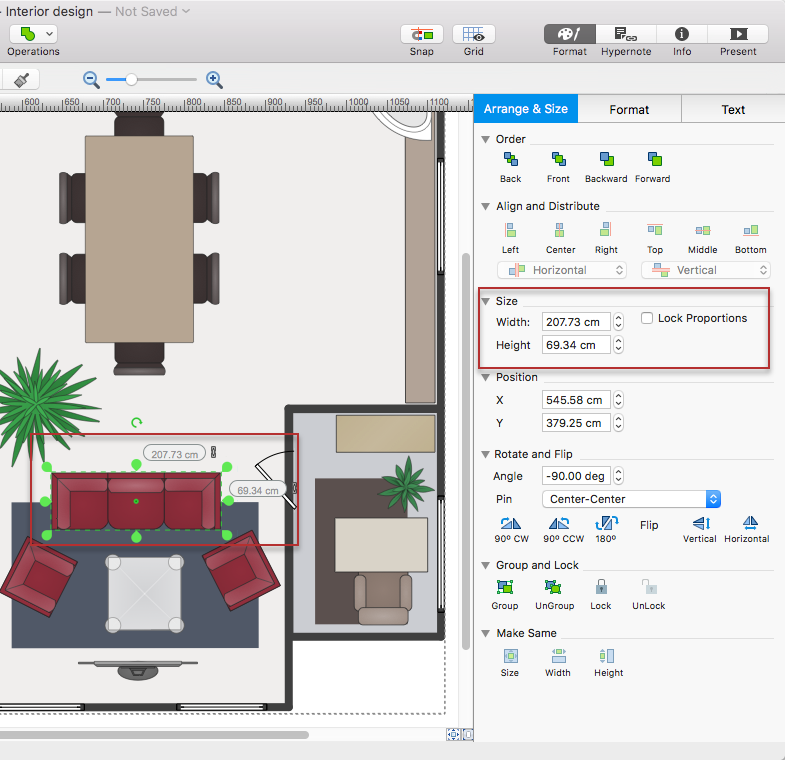
How to Resize Objects
HelpDesk
How to Change the Measurement Units and Drawing Scale
"Crow's Foot notation is used in Barker's Notation, SSADM and Information Engineering. Crow's Foot diagrams represent entities as boxes, and relationships as lines between the boxes. Different shapes at the ends of these lines represent the cardinality of the relationship." [Entity–relationship model. Wikipedia]
The vector stencils library ERD, crow's foot notation contains 18 symbols for creating the ER-diagrams using the ConceptDraw PRO diagramming nd vector drawing software.
The example"Design elements - ERD solution (crow's foot notation)" is included in the Entity-Relationship Diagram (ERD) solution from the Software Development area of ConceptDraw Solution Park.
Crow's foot ERD
.png--diagram-flowchart-example.png)
"Man-to-man defense is a type of defensive tactic used in team sports such as American football, association football, basketball, and netball, in which each player is assigned to defend and follow the movements of a single player on offense. Often, a player guards his counterpart (e.g. center guarding center), but a player may be assigned to guard a different position. The strategy is not rigid however, and a player might switch assignment if needed, or leave his own assignment for a moment to double team an offensive player. The term is commonly used even in women's basketball, though the gender-neutral 'player-to-player' also has some usage. ...
When defending the ball (i.e. guarding the man with the basketball) away from the basket in basketball, players typically should use a version of the following technique: The defender stands and faces the opponent. He is positioned between the ball and the basket and may be angled in one direction or another depending on the defensive scheme of that defender's team. He has his feet positioned beyond shoulder width with most of the weight distributed to the balls of his feet. However, the defender's heels should not be off the floor as this will put him off balance. The defender's knees should be bent at roughly a ninety degree angle with the bottom of his thighs parallel to the ground. This will place the defenders buttocks in a seated position. The defenders back should be straight with just a slight tilt forward. This will place the defender's head over the center of his body and maintain proper balance. Depending on the teachings of his coach, the defender should position his hands wide as if he were stretching his wingspan or place one hand high and one hand low." [Man-to-man defense. Wikipedia]
The basketball positions diagram example "Man-to-man basketball defense drill" was created using the ConceptDraw PRO diagramming and vector drawing software extended with the Basketball solution from the Sport area of ConceptDraw Solution Park.
www.conceptdraw.com/ solution-park/ sport-basketball
Basketball positions diagram

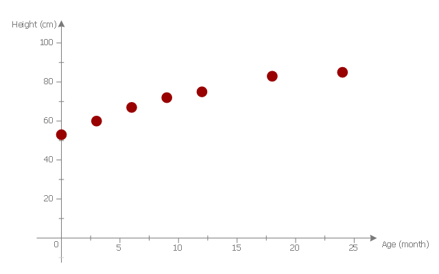
This scatter graph example visualize correlation between baby height and age.
"Human height is the distance from the bottom of the feet to the top of the head in a human body, standing erect. It is usually measured in centimetres when using the metric system, and feet and inches when using the imperial system. Human height has varied from under 60 centimetres (2 ft 0 in) to over 260 centimetres (8 ft 6 in). On average, males are taller than females. ...
Growth in stature, determined by its various factors, results from the lengthening of bones via cellular divisions chiefly regulated by somatotropin (human growth hormone (hGH)) secreted by the anterior pituitary gland. ...
The majority of linear growth occurs as growth of cartilage at the epiphysis (ends) of the long bones which gradually ossify to form hard bone. The legs compose approximately half of adult human height, and leg length is a somewhat sexually dimorphic trait. Some of this growth occurs after the growth spurt of the long bones has ceased or slowed. The majority of growth during growth spurts is of the long bones. Additionally, the variation in height between populations and across time is largely due to changes in leg length. The remainder of height consists of the cranium. Height is sexually dimorphic and statistically it is more or less normally distributed, but with heavy tails." [Human height. Wikipedia]
The scatter plot example "Baby height by age" was created using the ConceptDraw PRO diagramming and vector drawing software extended with the Scatter Diagrams solution from the Graphs and Charts area of ConceptDraw Solution Park.
Scatter diagram
Server rack diagrams visualize the the rack mounting of computer and network equipment as the drawing of frontal view of the rack with equipment installed. They are used for choosing the equipment or racks to buy, and help to organize equipment on the racks virtually, without the real installation.
"A 19-inch rack is a standardized frame or enclosure for mounting multiple equipment modules. Each module has a front panel that is 19 inches (482.6 mm) wide, including edges or ears that protrude on each side which allow the module to be fastened to the rack frame with screws." [19-inch rack. Wikipedia]
"A rack unit, U or RU is a unit of measure that describes the height of equipment designed to mount in a 19-inch rack or a 23-inch rack. The 19-inch (482.6 mm) or 23-inch (584.2 mm) dimension refers to the width of the equipment mounting frame in the rack including the frame; the width of the equipment that can be mounted inside the rack is less. One rack unit is 1.75 inches (4.445 cm) high.
The size of a piece of rack-mounted equipment is frequently described as a number in "U". For example, one rack unit is often referred to as "1U", 2 rack units as "2U" and so on.
A typical full size rack is 42U, which means it holds just over 6 feet of equipment, and a typical "half-height" rack would be 18-22U, or around 3 feet high." [Rack unit. Wikipedia]
The rack diagram template is included in the Rack Diagrams solution from the Computer and Networks area of ConceptDraw Solution Park.
Rack diagram template

ERD Symbols and Meanings

- Fiba Basketball Court Dimensions Feet
- Badminton Court Height In Feet
- Plant Layout Plans | Futsal Court Dimensions In Feet
- Basketball Court Dimensions | Football Ground Measurement In Feet
- Smartdraw Crows Feet
- Entity Relationship Diagram - ERD - Software for Design Crows Foot ...
- Design elements - Soccer silhouettes | Feet Kick Silhouette
- Hydrologic Furniture Feet Pic
- Food Court | Erd Chicken Feet
- How To Feet Pvc Pipe Electrical Pipe Diagram
- What Is Entity Relationship Diagram Using Crews Feet
- ERD Symbols and Meanings | Crows Feet Meaning
- Explain The Difference Between Chen And Crows Feet Notation I Erds
- Powerpoint Crows Feet Connector
- Difference Between Chen And Crows Feet Notation I Erds
- Crows Feet Notation
- Ice Hockey Rink Dimensions
- Crows Feet Diagram For Bank Management System
- Ice Hockey Rink Dimensions | Basketball Court Dimensions | Soccer ...
- Crows Feet Engineering