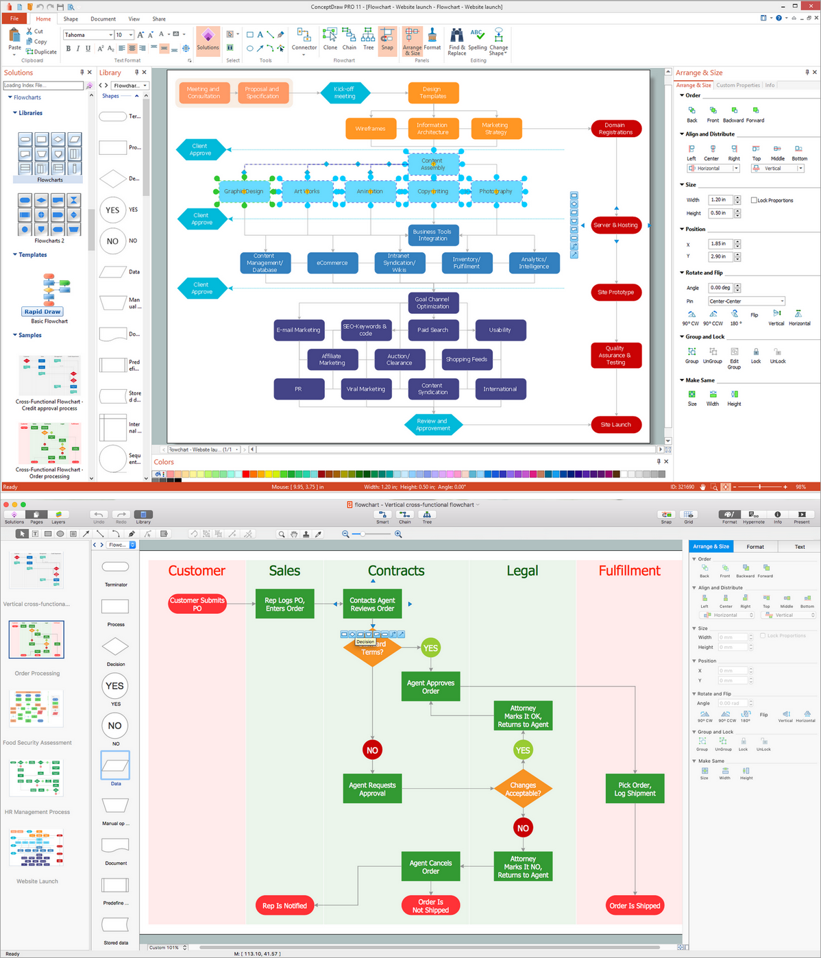
Basic Flowchart Symbols and Meaning


Flowchart Software
Entity Relationship Diagram Examples


Entity Relationship Diagram Examples
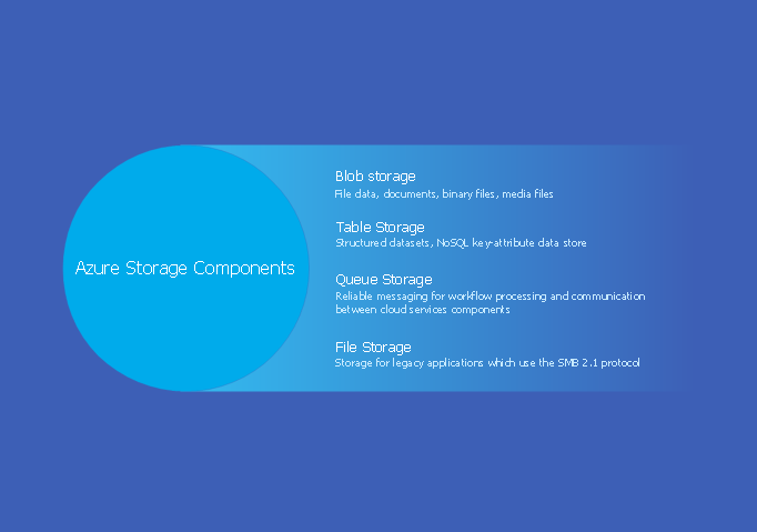
Azure Storage
UML Class Diagram Generalization Example UML Diagrams

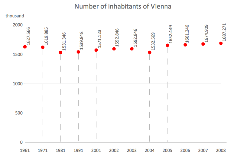
Scatter Chart Examples
Entity Relationship Diagram Symbols

Pyramid Diagram

 AWS Architecture Diagrams
AWS Architecture Diagrams with powerful drawing tools and numerous predesigned Amazon icons and AWS simple icons is the best for creation the AWS Architecture Diagrams, describing the use of Amazon Web Services or Amazon Cloud Services, their application for development and implementation the systems running on the AWS infrastructure. The multifarious samples give you the good understanding of AWS platform, its structure, services, resources and features, wide opportunities, advantages and benefits from their use; solution’s templates are essential and helpful when designing, description and implementing the AWS infrastructure-based systems. Use them in technical documentation, advertising and marketing materials, in specifications, presentation slides, whitepapers, datasheets, posters, etc.
- Point Of Sale Process Flow Diagram
- Flowchart Points Of Sales
- Purpose Of Annotation Symbol In Flowchart
- Flowchart Off Page Reference Example
- Predefined Process Flow Chart Example
- Process Diagram For A Point Of Sale
- Flowchart - Vector stencils library | Design elements - Accounting ...
- Sales flowchart - Vector stencils library | HR flowchart - Vector ...
- What Is A Predefined Process In Flowcharting
- Comment In Flow Chart Is Represented By Which Symbol