UML Deployment Diagram. Design Elements

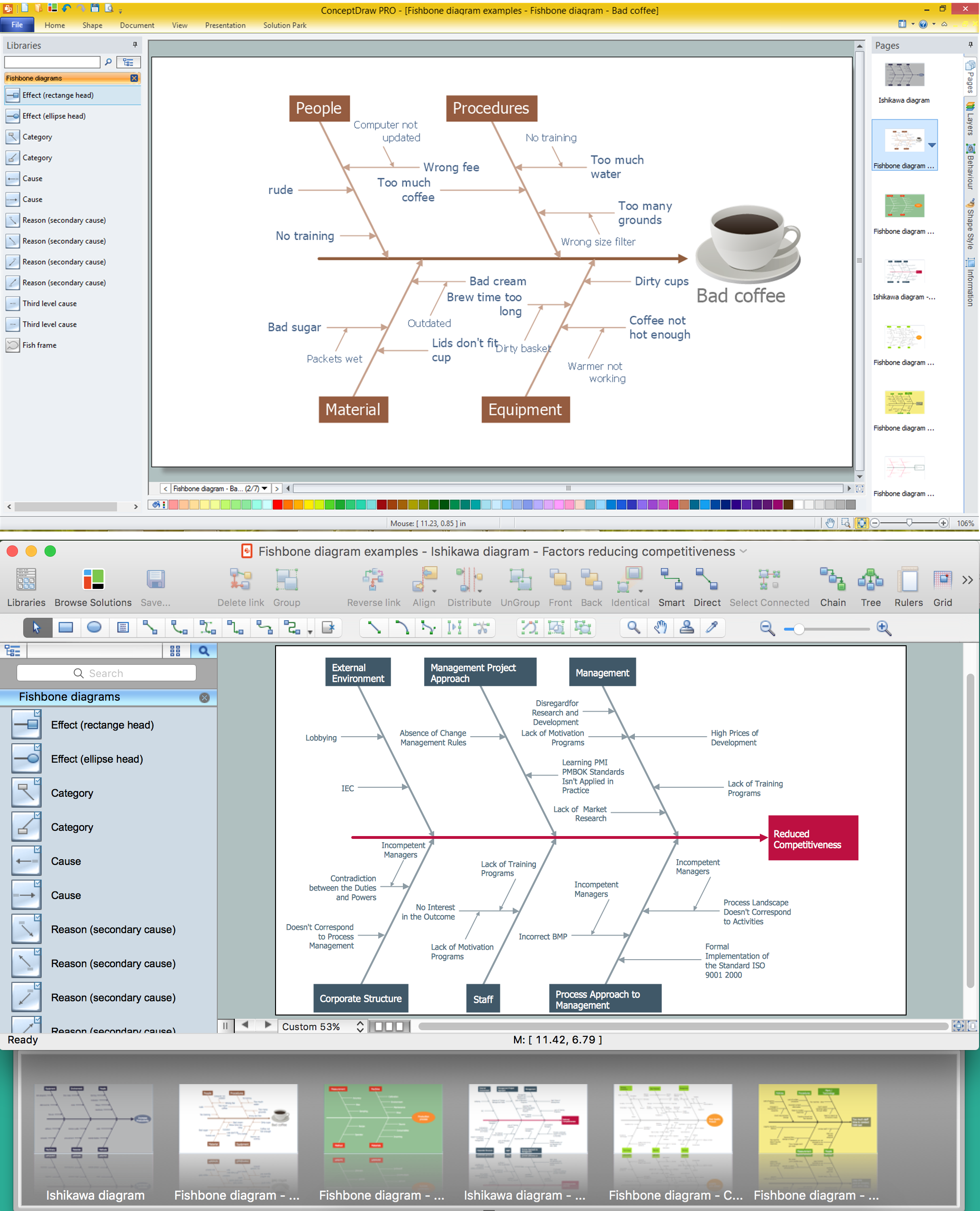
Using Fishbone Diagrams for Problem Solving
Network Diagram Software. LAN Network Diagrams. Physical Office Network Diagrams


Venn Diagram Examples for Problem Solving. Environmental Social Science. Human Sustainability Confluence

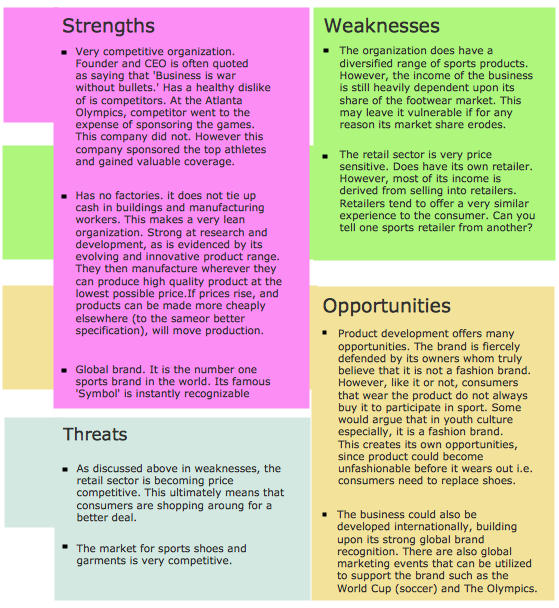
Competitor Analysis

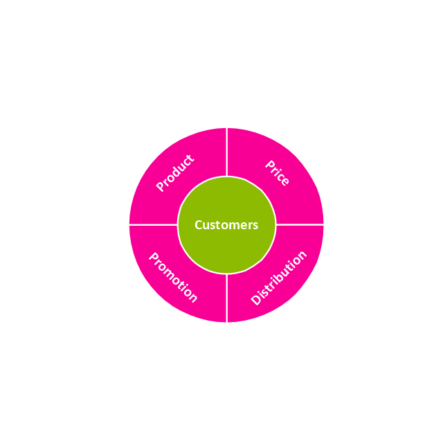
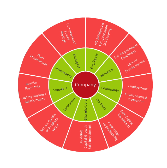
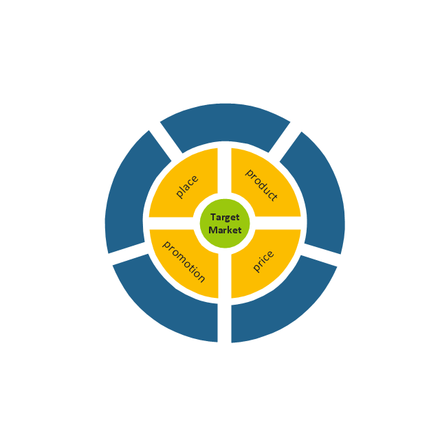
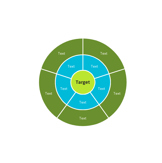
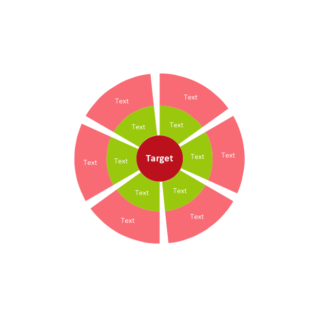
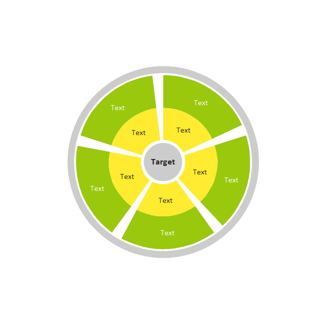
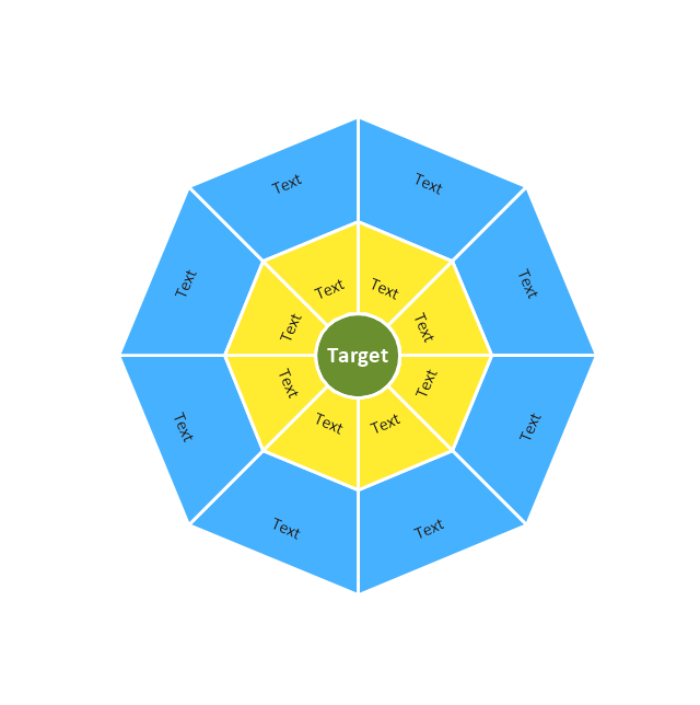
The vector stencils library "Target diagrams" contains 13 templates of target diagrams: marketing mix diagram, principles of marketing diagram, circle diagram, macro-micro environment diagram, stakeholder diagram, target market scope diagram.
Use these shapes to illustrate your marketing and sales documents, presentations, webpages and infographics in the ConceptDraw PRO diagramming and vector drawing software extended with the Target and Circular Diagrams solution from the Marketing area of ConceptDraw Solution Park.
www.conceptdraw.com/ solution-park/ marketing-target-and-circular-diagrams
Principles of marketing by Ph. Kotler

Marketing mix
Target

Principles of marketing by Ph. Kotler (prompt)
-target-diagrams---vector-stencils-library.png--diagram-flowchart-example.png)
Circle diagram

Macro-micro environmental forces diagram
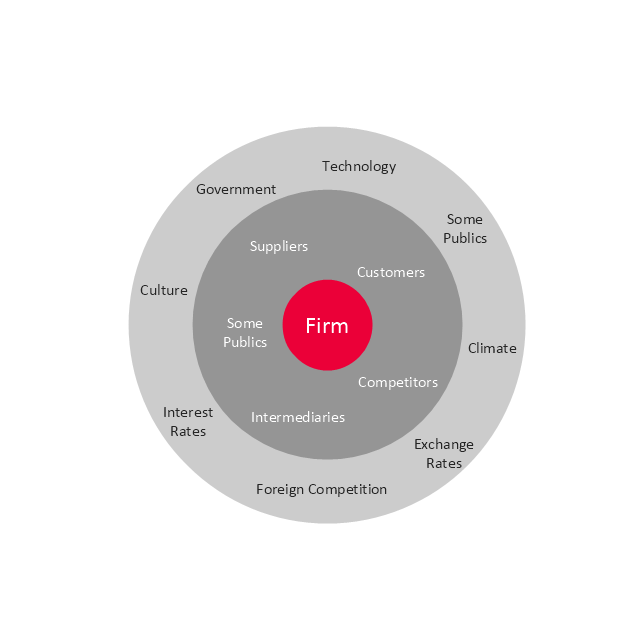
Macro-micro environmental forces diagram (prompt)
-target-diagrams---vector-stencils-library.png--diagram-flowchart-example.png)
Stakeholder diagram
Target market scope diagram
Target diagram 1
Target diagram 2
Target diagram 3
Target diagram
The vector stencils library "Bank UML deployment diagram" contains 10 shapes for drawing UML deployment diagrams.
Use it for object-oriented modeling of your bank information system.
"A deployment diagram in the Unified Modeling Language models the physical deployment of artifacts on nodes. To describe a web site, for example, a deployment diagram would show what hardware components ("nodes") exist (e.g., a web server, an application server, and a database server), what software components ("artifacts") run on each node (e.g., web application, database), and how the different pieces are connected (e.g. JDBC, REST, RMI).
The nodes appear as boxes, and the artifacts allocated to each node appear as rectangles within the boxes. Nodes may have subnodes, which appear as nested boxes. A single node in a deployment diagram may conceptually represent multiple physical nodes, such as a cluster of database servers.
There are two types of Nodes:
1. Device Node.
2. Execution Environment Node.
Device nodes are physical computing resources with processing memory and services to execute software, such as typical computers or mobile phones. An execution environment node (EEN) is a software computing resource that runs within an outer node and which itself provides a service to host and execute other executable software elements." [Deployment diagram. Wikipedia]
This example of UML deployment diagram symbols for the ConceptDraw PRO diagramming and vector drawing software is included in the ATM UML Diagrams solution from the Software Development area of ConceptDraw Solution Park.
UML deployment diagram symbols

Simple Drawing Applications for Mac
UML Diagram Types List

SWOT Analysis
UML Deployment Diagram Example - ATM System UML diagrams

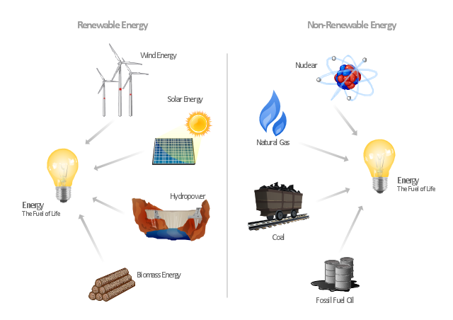
"Consumption of energy resources, (e.g. turning on a light) requires resources and has an effect on the environment. Many electric power plants burn coal, oil or natural gas in order to generate electricity for energy needs. While burning these fossil fuels produces a readily available and instantaneous supply of electricity, it also generates air pollutants including carbon dioxide (CO2), sulfur dioxide and trioxide (SOx) and nitrogen oxides (NOx). Carbon dioxide is an important greenhouse gas which is thought to be responsible for some fraction of the rapid increase in global warming seen especially in the temperature records in the 20th century, as compared with tens of thousands of years worth of temperature records which can be read from ice cores taken in Arctic regions. Burning fossil fuels for electricity generation also releases trace metals such as beryllium, cadmium, chromium, copper, manganese, mercury, nickel, and silver into the environment, which also act as pollutants.
The large-scale use of renewable energy technologies would "greatly mitigate or eliminate a wide range of environmental and human health impacts of energy use". Renewable energy technologies include biofuels, solar heating and cooling, hydroelectric power, solar power, and wind power. Energy conservation and the efficient use of energy would also help." [Energy industry. Environmental impact. Wikipedia]
The Energy resources diagram example was created in the ConceptDraw PRO diagramming and vector drawing software using the Manufacturing and Maintenance solution from the Illustration area of ConceptDraw Solution Park.
Infographics
Fishbone Diagram Template

- Marketing Environment Diagram Chart
- Venn Diagram Examples for Problem Solving. Environmental Social ...
- Competitive Environment With Diagram
- Venn Diagram Examples for Problem Solving. Environmental Social ...
- Diagram Of Micro And Macro Environment
- The Venn Diagram Of The Three Business Environment Micro ...
- Environment Diagrams
- Competitor Analysis | Block diagram - Porter's five forces model ...
- Diagram Of Business Environment Showing The Links Between
- Environment Flow Chart Diagrams
- Target diagrams - Vector stencils library | Competitor Analysis ...
- Diagram To Show Micro And Macro Environment
- Examples For Environment On Cause And Effect Diagram
- Matrix Organization Structure | Components of ER Diagram | UML ...
- File Processing System Environment Diagram
- Process Flowchart | UML Deployment Diagram . Design Elements ...
- Diagram To Illustrate File Processing System Environment
- Steps To Draw Diagram Of Environment
- Draw A Diagram To Illustrate File Processing System Environment
- Target Diagram