Electrical Symbols, Electrical Diagram Symbols
How to create Electrical Diagram? It’s very easy! All you need is a powerful software. It wasn’t so easy to create Electrical Symbols and Electrical Diagram as it is now with electrical diagram symbols offered by the libraries of Electrical Engineering Solution from the Industrial Engineering Area at the ConceptDraw Solution Park.This solution provides 26 libraries which contain 926 electrical symbols from electrical engineering: Analog and Digital Logic, Composite Assemblies, Delay Elements, Electrical Circuits, Electron Tubes, IGFET, Inductors, Integrated Circuit, Lamps, Acoustics, Readouts, Logic Gate Diagram, MOSFET, Maintenance, Power Sources, Qualifying, Resistors, Rotating Equipment, Semiconductor Diodes, Semiconductors, Stations, Switches and Relays, Terminals and Connectors, Thermo, Transformers and Windings, Transistors, Transmission Paths,VHF UHF SHF.
Wiring Diagrams with ConceptDraw DIAGRAM
A wiring diagram is a comprehensive diagram of each electrical circuit system showing all the connectors, wiring, terminal boards, signal connections (buses) between the devices and electrical or electronic components of the circuit. It also identifies the wires by wire numbers or colour coding. Wiring diagrams are necessary to troubleshoot and fix electrical or electronic circuits.
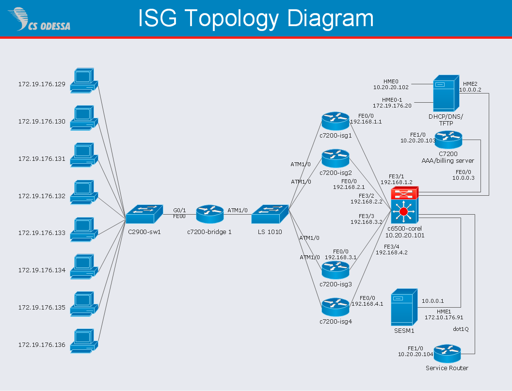
Network Diagram Software ISG Network Diagram
Drawing ISG Network Diagram using ConceptDraw DIAGRAM stencilsHelpDesk
How to Support Your Mind Map with Visual Elements
Symbols and images that you can add to ideas in your mind map help to extend the meaning and add context to topics. These visual elements can be used to depict priority, types of actions (phone calls, meetings, emails, etc), and kinds of information or ideas. You can easily incorporate images and symbols into your mind maps making them even more memorable and brain friendly.The vector stencils library "Resistors" contains 14 element symbols of resistors for drawing electronic schematics, circuit diagrams and electrical drawings.
"A resistor is a passive two-terminal electrical component that implements electrical resistance as a circuit element. Resistors act to reduce current flow, and, at the same time, act to lower voltage levels within circuits. Resistors may have fixed resistances or variable resistances, such as those found in thermistors, varistors, trimmers, photoresistors and potentiometers.
The current through a resistor is in direct proportion to the voltage across the resistor's terminals. This relationship is represented by Ohm's law ...
Resistors are common elements of electrical networks and electronic circuits and are ubiquitous in electronic equipment. Practical resistors can be composed of various compounds and films, as well as resistance wires (wire made of a high-resistivity alloy, such as nickel-chrome). Resistors are also implemented within integrated circuits, particularly analog devices, and can also be integrated into hybrid and printed circuits." [Resistor. Wikipedia]
The shapes example "Design elements - Resistors" was drawn using the ConceptDraw PRO diagramming and vector drawing software extended with the Electrical Engineering solution from the Engineering area of ConceptDraw Solution Park.
Circuits and Logic Diagram Software
ConceptDraw DIAGRAM provides Electrical Engineering solution from the Industrial Engineering Area of ConceptDraw Solution Park.Electrical Engineering solution helps you create quick and easy: Electrical schematics, Digital and analog logic designs, Circuit and wiring schematics and diagrams, Power systems diagrams, Maintenance and repair diagrams, Circuit board and amplifier diagrams, Integrated circuit schematics.
IDEF0 Flowchart Symbols
The IDEF0 method is built on the functional modeling language Structured Analysis and Design Technique (SADT) and focuses on activity modeling. The ability to create the IDEF0 flowcharts and business diagrams rapidly and without efforts is made possible thanks to wide range of intuitive tools of ConceptDraw DIAGRAM software and IDFE0 notation supplied by IDEF0 Diagrams solution from the Software Development area. This solution is rich for the ready-to-use specific IDEF0 flowchart symbols grouped in IDEF0 Diagram library.Computer and Networks Area
The solutions from Computer and Networks Area of ConceptDraw Solution Park collect samples, templates and vector stencils libraries for drawing computer and network diagrams, schemes and technical drawings.
HR Flowcharts
Human resource management diagrams show recruitment models, the hiring process and human resource development of human resources.
HelpDesk
How to Connect an Image to a Topic in Your Mind Map
There is nothing easier than adding images to your mind map. Images can add creativity and functionality, and give your map a distinct style. ConceptDraw MINDMAP has a Graphics panel containing a clip art gallery so you can easily incorporate pictures into your maps making them even more memorable and intuitive. You can add images to any part of your mind map.
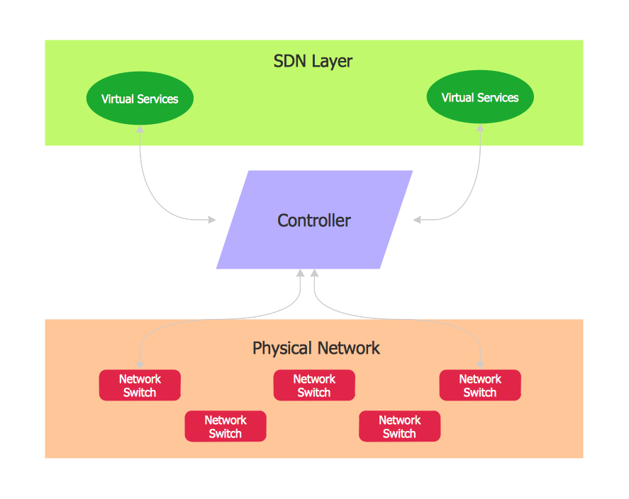
Software Defined Networking System Overview
Software-Defined Networking (SDN) is a new powerful concept for decision these problems. SDN proposes to disaggregate the traditional networking stacks that are vertically integrated to customize the network operations for specialized environments and improve network service velocity.On this example you can see the Software-Defined Networking (SDN) diagram that was created in ConceptDraw DIAGRAM using the Computer and Networks Area of ConceptDraw Solution Park.
HelpDesk
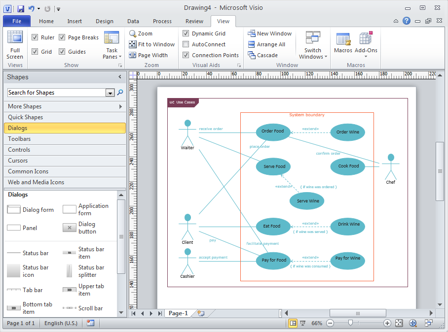
How to Convert ConceptDraw DIAGRAM v12 file into MS Visio 2003-2010 format
Many people use the MS Visio as a business graphic creation program. It is a powerful application with advanced ability to support complex solutions. The native file format for Visio 2010 and earlier files is VSD. ConceptDraw DIAGRAM supports export to Visio XML files (VDX). The transfer process is very simple. You can easily share your ConceptDraw Documents with MS Visio 2007/2010 users. changing software products, you can keep all your documents, created in MS Visio. Using ConceptDraw DIAGRAM, the same as using MS Visio , you will have an opportunity to work with powerful content, provided by Solution Park. You can create various documents with no need to look for the necessary elements for your diagrams in other software products.Microsoft Azure
Microsoft Azure is widely used cloud platform which was created by Microsoft and now is managed by Microsoft datacenters in 19 regions of the world, and has a wide set of benefits and features.ConceptDraw DIAGRAM diagramming and vector drawing software extended with Azure Architecture Solution from the Computer and Networks area of ConceptDraw Solution Park is the best for designing various pictorial infographics, illustrations and materials showing the possibilities and work of Microsoft Azure Cloud System and Azure services.
HelpDesk
How to Open Visio® VDX File Using ConceptDraw DIAGRAM
MS Visio file with the extention.VDX can be created with the MS Visio 2003-2007. It is a filename extension for the MS Visio XML drawing file format. MS Visio 2010 and earlier versions support reading and writing files in a binary VSD or xml-based VDX file formats. Since MS Visio 2013 drawing files are written in the new VSDX and VSDM file formats. The writing VDX files is no longer supported. If you used MS Visio 2003-2010 before and now is considering to switch to ConceptDraw DIAGRAM, maybe this is a good news - ConceptDraw DIAGRAM is still supported reading and writing of Microsoft Visio XML file format. Thus replacing the diagramming software , allows to keep all your drawings, created in the old versions of MS Visio. Making business drawings with ConceptDraw DIAGRAM is easier than using MS Visio. Moreover, you will be able to use a huge number of business-oriented libraries supplied by ConceptDraw Solution Park. Also, using ConceptDraw you can create your custom objects and supplement libraries to cover your requirements.- Telecommunication Network Diagrams | How to Create a ...
- Design elements - Integrated circuit | Electrical Diagram Symbols ...
- Design elements - Local vehicular networking | Local vehicular ...
- Design elements - Logic gate diagram | Electrical Diagram Symbols ...
- Electrical Diagram Symbols | Wiring Diagrams with ConceptDraw ...
- Cisco IBM. Cisco icons, shapes, stencils and symbols | Aircraft ...
- Network hardware - Vector stencils library | Design elements ...
- Cisco Routers. Cisco icons, shapes, stencils and symbols | Cisco ...
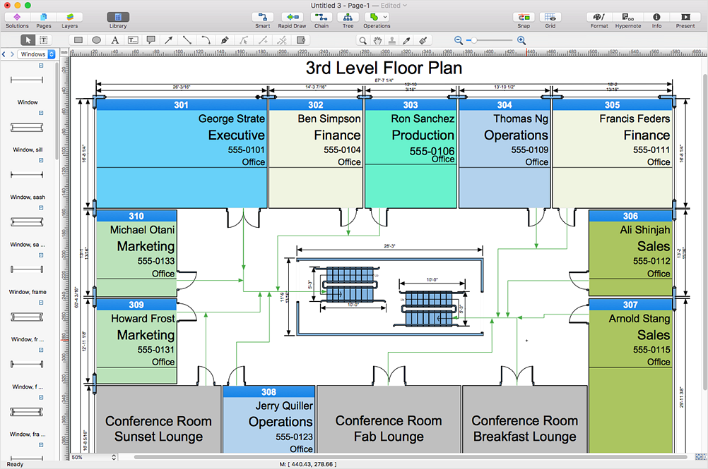
- Design elements - Network layout floorplan | Local area network ...
- Network Gateway Router | Cisco Routers. Cisco icons, shapes ...
- Design elements - Initiation and annunciation | Network hardware ...
- Cisco LAN. Cisco icons, shapes, stencils and symbols | Design ...
- Design elements - Machines and equipment | UML Flowchart ...
- Symbol Of The Elements Of Electronic Component Used In Circuit
- Network Topologies | Design elements - Cisco WAN | Computer ...
- Design elements - Computers and Apple machines | Design ...
- Design elements - Power sources | Design elements - Integrated ...
- Electrical Drawing Software | Design elements - Electrical circuits ...
- Cisco Routers. Cisco icons, shapes, stencils and symbols | Cisco ...
- Router Symbols In Networking
- ERD | Entity Relationship Diagrams, ERD Software for Mac and Win
- Flowchart | Basic Flowchart Symbols and Meaning
- Flowchart | Flowchart Design - Symbols, Shapes, Stencils and Icons
- Flowchart | Flow Chart Symbols
- Electrical | Electrical Drawing - Wiring and Circuits Schematics
- Flowchart | Common Flowchart Symbols