HelpDesk
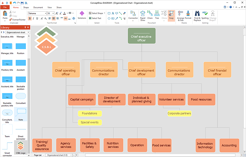
How to Add a Self-Drawn Object to a Library
Electrical Drawing Software and Electrical Symbols

Data Flow Diagram Symbols. DFD Library

Electrical Symbols, Electrical Diagram Symbols

Process Flow Diagram Symbols

Local area network (LAN). Computer and Network Examples
 diagram")

Mechanical Drawing Symbols

HelpDesk
How to Create a Map of Germany

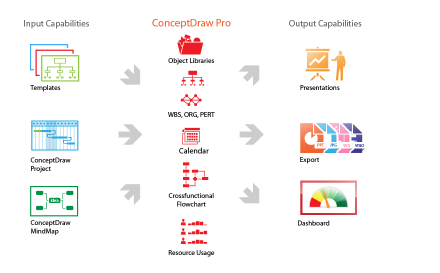
Technical Drawing Software

Product Overview
- How to Add a Self- Drawn Object to any Library | How to Contribute ...
- Basic Diagramming | How to Add a Self- Drawn Object to any Library ...
- Drawn Structure Of The Library Administrative Chart
- Computer network - Vector stencils library | Unified communications ...
- Bathroom - Vector stencils library | Design elements - Bathroom ...
- How to Add a Self- Drawn Object to any Library | How to Edit ...
- How to Add a Self- Drawn Object to any Library | Receiver Symbol ...
- Draw Floor Plan Of The Reception Area
- How To Draw The Map Of Ghana
- How to Add a Self- Drawn Object to any Library | Mobile satellite TV ...